


Get started with PYNQ-Z2 on Windows
- Official website: http://www.pynq.io
- Comparison source: http://www.pynq.io/board
- Supported browser (Chrome)
- Ethernet cable (connect with a computer)
- Micro USB cable (power)
- MicroSD card (Minimum 8GB)
The boot image on http://www.pynq.io/board.html is not available. Instead, we can get PYNQ-Z2 Boot Image V2.4 on http://www.tul.com.tw/ProductsPYNQ-Z2.html.
If we want to use the image file of Z1 on Z2, the audio system would not work. But the others may work with minor code change:
- Source: http://www.pynq.io/boardAfter downloading, write the unzipped image into the MicroSD card with win32Diskimager( https://sourceforge.net/projects/win32diskimager)
- Insert the MicroSD card into the slot (on the bottom)
- Set the jumper as MicroSD boot mode
- Connect the board with a computer (or router) with Ethernet cable
- Set the power jumper on USB and power pynq-z1 via Micro USB cable
- Turn on the power switch
- Wait for a while ...
password: xilinx
Via RouterCheck the ip address of the PYNQ Z2 board on a router. Then open a web browser and navigate to:
http://(ip):9090, where (ip) is the ip address of the board, e.g. http://192.168.1.102:9090 for mine.
Via ComputerSet the static ip address as 192.168.2.x where x is 0-255 (excluding 99, as this is already taken by the board). Then open a web browser and navigate to: http://192.168.2.99:9090 .
We can see the jupyter notebook in the browser and there are several folders.
Open board_btns_leds.ipynb in base>board and run the code. It will take some time to import BaseOverlay.
from time import sleep
from time import sleep

from pynq.overlays.base import BaseOverlay
from pynq.overlays.base import BaseOverlay

base = BaseOverlay("base.bit")
base = BaseOverlay("base.bit")

Delay1 = 0.3
Delay1 = 0.3

Delay2 = 0.1
Delay2 = 0.1

color = 0
color = 0

rgbled_position = [4,5]
rgbled_position = [4,5]

for led in base.leds:
for led in base.leds:

led.on()
led.on()

while (base.buttons[3].read()==0):# turn off the lights and end the demo
while (base.buttons[3].read()==0):# turn off the lights and end the demo

if (base.buttons[0].read()==1):# select the mode 1
if (base.buttons[0].read()==1):# select the mode 1

color = (color+1) % 8 # eight colors
color = (color+1) % 8 # eight colors

for led in rgbled_position:
for led in rgbled_position:

base.rgbleds[led].write(color)
base.rgbleds[led].write(color)

base.rgbleds[led].write(color)
base.rgbleds[led].write(color)

sleep(Delay1)
sleep(Delay1)


elif (base.buttons[1].read()==1):# select the mode 2
elif (base.buttons[1].read()==1):# select the mode 2

for led in base.leds:
for led in base.leds:

led.off()
led.off()

sleep(Delay2)
sleep(Delay2)

for led in base.leds:
for led in base.leds:

led.toggle()
led.toggle()

sleep(Delay2)
sleep(Delay2)


elif (base.buttons[2].read()==1):# select the mode 3
elif (base.buttons[2].read()==1):# select the mode 3

for led in reversed(base.leds):
for led in reversed(base.leds):

led.off()
led.off()

sleep(Delay2)
sleep(Delay2)

for led in reversed(base.leds):
for led in reversed(base.leds):

led.toggle()
led.toggle()

sleep(Delay2)
sleep(Delay2)


print('End of this demo ...')
print('End of this demo ...')

for led in base.leds:
for led in base.leds:

led.off()
led.off()

for led in rgbled_position:
for led in rgbled_position:

base.rgbleds[led].off()
base.rgbleds[led].off()
From the code, we can see that LED4 and LED5 are controlled by BTN0. When the code is running, the colors of LED4 and LED5 will change if BTN0 is pressed. And if BTN1 or BTN2 is pressed, LED0-LED3 will flicker forward or backward.
Now, we want LED4 and LED5 be turned on with different colors. Therefore, the code is changed as
if (base.buttons[0].read()==1):# select the mode 1
if (base.buttons[0].read()==1):# select the mode 1

color1 = (color1+1) % 8
color1 = (color1+1) % 8

color2 = (color1+1) % 8
color2 = (color1+1) % 8

# for led in rgbled_position:
# for led in rgbled_position:

base.rgbleds[4].write(color1)
base.rgbleds[4].write(color1)

base.rgbleds[5].write(color2)
base.rgbleds[5].write(color2)

sleep(Delay1)
sleep(Delay1)
BRAVO!It is quite convenient to perform hardware design with python! Once the logical parts (PL) have been well-designed, we can use python on a jupyter notebook to combine PL and PS to test our ideas.
- PL can be designed with vivado.
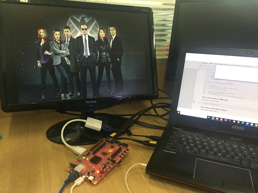
Maybe the LED test is not so attractive. We want to explore more. Therefore, open opencv_face_detect_hdmi.ipynb in base>video to perform face detection. An HDMI input source and HDMI output monitor are required for this code.
In this test, the algorithm is completed with the help of cv2 and numpy.
import cv2
import cv2

import numpy as np
import numpy as np

time.sleep(10)
time.sleep(10)

frame = hdmi_in.readframe()
frame = hdmi_in.readframe()

face_cascade = cv2.CascadeClassifier('/home/xilinx/jupyter_notebooks/base/video/data/'
face_cascade = cv2.CascadeClassifier('/home/xilinx/jupyter_notebooks/base/video/data/'

'haarcascade_frontalface_default.xml')
'haarcascade_frontalface_default.xml')

eye_cascade = cv2.CascadeClassifier('/home/xilinx/jupyter_notebooks/base/video/data/'
eye_cascade = cv2.CascadeClassifier('/home/xilinx/jupyter_notebooks/base/video/data/'

'haarcascade_eye.xml')
'haarcascade_eye.xml')

gray = cv2.cvtColor(frame, cv2.COLOR_BGR2GRAY)
gray = cv2.cvtColor(frame, cv2.COLOR_BGR2GRAY)

faces = face_cascade.detectMultiScale(gray, 1.3, 5)
faces = face_cascade.detectMultiScale(gray, 1.3, 5)

for (x,y,w,h) in faces:
for (x,y,w,h) in faces:

cv2.rectangle(frame,(x,y),(x+w,y+h),(255,0,0),2)
cv2.rectangle(frame,(x,y),(x+w,y+h),(255,0,0),2)

roi_gray = gray[y:y+h, x:x+w]
roi_gray = gray[y:y+h, x:x+w]

roi_color = frame[y:y+h, x:x+w]
roi_color = frame[y:y+h, x:x+w]


eyes = eye_cascade.detectMultiScale(roi_gray)
eyes = eye_cascade.detectMultiScale(roi_gray)

for (ex,ey,ew,eh) in eyes:
for (ex,ey,ew,eh) in eyes:

cv2.rectangle(roi_color,(ex,ey),(ex+ew,ey+eh),(0,255,0),2)
cv2.rectangle(roi_color,(ex,ey),(ex+ew,ey+eh),(0,255,0),2)
FPGA is utilized to get access to peripheral equipments, such as display the image with HDMI.
hdmi_out.writeframe(frame)
hdmi_out.writeframe(frame)
- The screenshot happens too fast for us to switch the picture. So we use time.sleep(10) to delay hdmi_in.readframe().
Finally, the monitor is turned on through HDMI. However, Clark Gregg is not detected possibly because of the sunglass.Obviously, this algorithm cannot reach the standard of S.H.I.E.L.D. .
The examples above are completed by calling the FPGA interface in PL. However, the algorithms are still running on the Arm core. If better performance is desired, the algorithm can be designed and accelerated with HDL.


Comments
Please log in or sign up to comment.