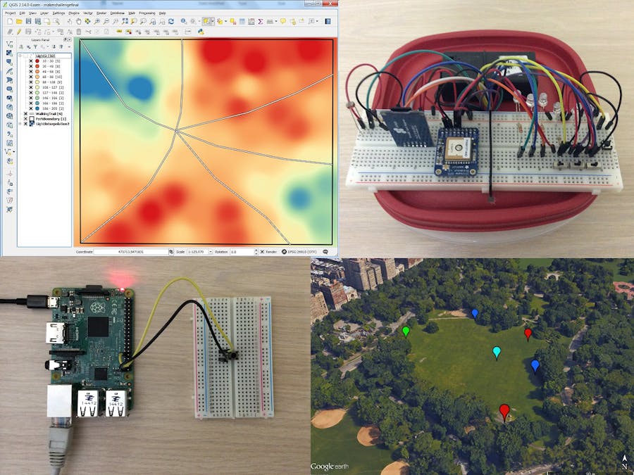
Current mobile technology has become very advanced and easy to use with GIS information maps available on almost every type of device. This project can be made into a classroom activity to teach children the basics of open source hardware, mobile computing, geospatial technologies, and cloud computing.
This project consists of 3 parts:
1) Arduino GPS Datalogger
With assistance, young children could build a device that records GPS location information, light measurement, and the type of thing being located. They could go outdoors and mark the locations of predetermined things (signs, trees, park benches, etc...). This provides a better understanding of the world around them and a better appreciation for the data displayed on GIS maps. Low light levels at night in public areas can be a safety concern. Accompanied by an adult they could go out at night to collect light measurements for further analysis.
2) GIS Visualization and Analysis
Visualize the location collected in the field on a map. Estimate the light levels for an area by performing spatial point interpolation analysis and display the results on a map.
3) Using Windows 10 IoT Core and Azure IoT Hub
After performing GIS visualization and analysis, use Windows 10 IoT Core and Azure IoT Hub to upload and distribute the data. This allows the system to easily scale up to support data management on thousands of data collectors and devices in the field.
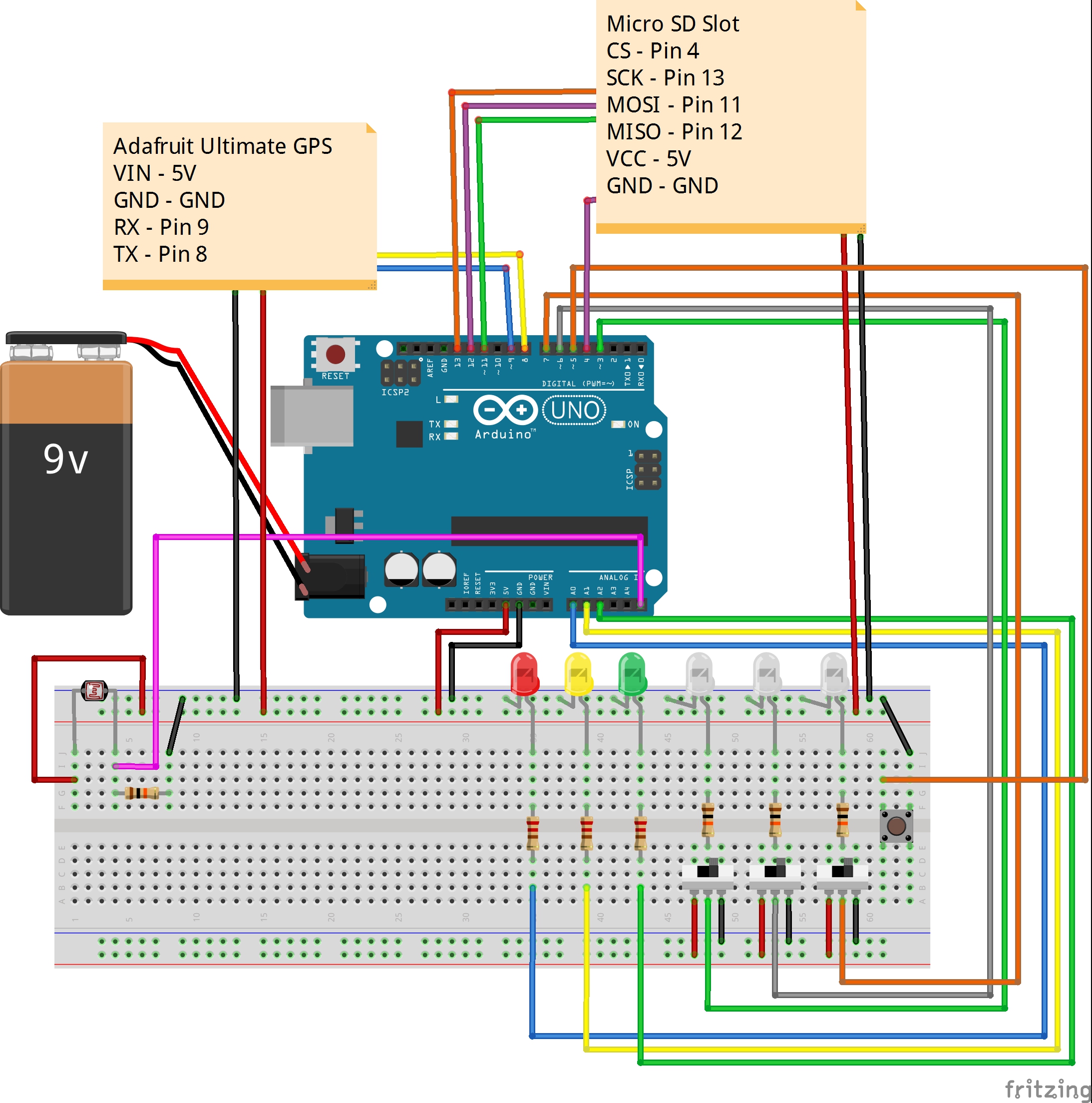
Arduino GPS DataloggerThe following video gives and overview of the Arduino Uno GPS Datalogger device and a quick demonstration. Source code and breadboard diagram can be found below.
Here's some more information about the components.
Photoresistor
These analog sensors measure the brightness of light and are very easy to use. See and example with source code here. The analog reading will measure 0 - 1023 but most readings will be under 200 unless the light is very bright. When building your device, try out some light readings so you know what to expect.
Ex. bright sunlight is about 1000, daytime outdoor shade is about 900, and directly under a street light at night is about 170.
Micro SD Slot
Good example can be found in the Arduino IDE under File > Examples > SD > Datalogger.
Adafruit Ultimate GPS
Easy to use GPS. Follow the examples here to install the GPS libraries into your Arduino IDE.
Satellite Fix Status LEDs
Horizontal Dilution of Precision (HDOP) is a measurement of X,Y positional accuracy coming from the GPS. The lower the HDOP value, the more accurate the position. If the GPS has a fix it will return the HDOP value with the latitude and longitude position. More information on GPS Dilution of Precision here.
- Red - No satellite fix
- Yellow - Satellite fix with HDOP > 1.5.
- Green - Satellite fix with HDOP <= 1.5.
Binary Feature Type Slide Switches
Three slide switches are used for the binary representation of base 10 0 - 7. The leftmost switch represents 2^2 or 4. The center switch represents 2^1 or 2. The rightmost switch represents 2^0 or 1. Adding the values based on the switch state gives the 0 - 7 base 10 number that corresponds to the type of feature being collected. Ideally the person using the Arduino GPS Datalogger would understand what the code means.
For Example:
OFF OFF OFF = 0 0 0 = 0 = Light Sensor Reading
OFF OFF ON  = 0 0 1 = 1 = Park Bench
OFF ON  OFF = 0 1 0 = 2 = Rock
OFF ON  ON  = 0 1 1 = 3 = Garbage Can
ON  OFF OFF = 1 0 0 = 4 = Tree
ON  OFF ON  = 1 0 1 = 5 = Payphone
ON  ON  OFF = 1 1 0 = 6 = Lamppost
ON  ON  ON  = 1 1 1 = 7 = Water Fountain
Button
Every time the button is pressed, the device appends to a line of comma separated values (CSV) text to datalog.csv on the microSD card.
The data is in the format of:
LATITUDE,LONGITUDE,LIGHT_VALUE,FEATURE_TYPE
- LATITUDE and LONGITUDE come from the GPS.
- LIGHT_VALUE is the analog reading from the photoresistor.
- FEATURE_TYPE is the 0 - 7 value depending on the on/off settings of the 3 binary switches described above.
CSV Data Example:
40.77221,-73.97392,105,5
40.77139,-73.97394,60,1
40.77051,-73.97460,150,6
40.77225,-73.97650,25,3
40.77171,-73.97462,43,2
40.77283,-73.975033,54,1
No LCD Display?
The multiple LEDs could have been replaced with a 1602 LCD screen and some more buttons but there were issues.
- Having the code for the GPS, microSD card slot, and a 1602 LCD would compile and deploy to the Arduino Uno, but the microSD card slot was not stable. Removing the LCD stabilized the microSD card slot so LEDs were added to provide sufficient user notification. Using an Arduino device with more resources such as the MEGA would probably allow for a 1602 LCD along with the GPS and microSD card slot.
- The 9V battery is convenient for the Arduino GPS Datalogger, but the battery it does not last long when powering the 1602 LCD display. It wasn't a critical component so it had to go.
Visualizing the GPS Points
Having GIS data in CSV format is great but not very useful unless you can see it on a map. Eject the microSD card from the Arduino GPS Datalogger and insert in into a Windows 10 computer with Google Earth Professional installed. Go here for installation and licensing instructions. Copy the text file from the microSD card to the computer and open it in a text editor. Add the following line as a column heading at the top of the text file and save it as a .CSV file.
LATITUDE,LONGITUDE,LIGHT_VALUE,FEATURE_TYPE
Using Google Earth Professional go to the File menu and choose Import... Browse for the .CSV file and import it. Go through the options to create different map styles for the icons representing the different feature types and display the point locations in Google Earth Professional. The Professional version of Google Earth must be used. The regular version of Google Earth does not have the ability to import a .CSV file.
Spatial Analysis With Quantum GIS (QGIS)
QGIS is a popular free opensource GIS with the installer and tutorials available here. Using QGIS you can perform spatial analysis on the light sensor attribute for the GPS location to identify areas of sufficient and insufficient lighting at night in a public area such as a park.
Step 1 - Load the boundary, walking trails and other relevant information about the area being assessed for insufficient lighting.
Step 2 - Load the points from the .CSV file coming from the GPS Datalogger into the QGIS map. Apply the point symbology and labels so you can visually see the light values.
The points will display the light sensor values so you can see where is bright (blue) and where it is dark (red). Viewing only the point data is not sufficient when trying to analyze the larger area.
Step 3 - Perform an interpolation on the point data to get a better understanding of the area surrounding and between the points. Interpolation is used when you have data for certain locations and want to estimate the values between the known locations. More information on interpolation here.
The interpolation provides a better picture of the light values within the park. This analysis can be improved by supplying more light sensor readings at known locations.
Step 4 - Go collect more light sensor readings and load them into QGIS.
Step 5 - Rerun the interpolation on the larger dataset.
You can see that the second interpolation shows a similar pattern to the first interpolation but it has more detail because of the additional points.
Using Windows 10 IoT Core and Azure IoT Hub.Scaling Up
The Arduino GPS Datalogger is a cheap and simple device that can record sensor information to a microSD card. These devices could be widely geographically distributed to collect information. Managing the information coming from these devices could be a challenging task if you needed to design a system to do so.
By using Windows 10 IoT Core and Azure IoT Hub as the foundation of a messaging system, the number of devices could be easily scaled up to thousands of devices supplying information.
First Try These Examples
Before proceeding, it is highly recommended that you follow the Getting Started with Azure IoT Hub for .NET tutorial. The getting started tutorial will take you through the steps of creating an Azure trial account, setting up an Azure IoT Hub and develop the core samples allowing you to send and receive IoT Hub messages.
Also download the Azure IoT Hub Device Explorer for easy administration of the Windows 10 IoT Core devices connecting to your Azure IoT Hub. Download the source and/or installer from here.
Windows 10 IOT Core on Raspberry Pi 2
Using a Windows 10 development machine, download the Windows 10 IoT Core for Raspberry Pi 2 and flash an micoSD card using the Windows IoT Image Helper.
Mount the microSD card in the Raspberry Pi 2, plug it in to ethernet, and make sure it is listed in the Windows IoT Core Watcher on the development machine when it boots up.
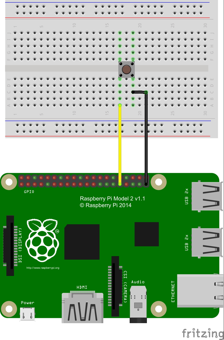
Connect a button on a breadboard as showed in the picture below. See schematic at the bottom of this page. Links to the following source code can also be found at the bottom of this page.
Universal Windows Application for Data Upload
Start up Visual Studio 2015 on a Windows 10 computer and choose File > New > Project. Choose the Blank App template for the Universal Windows Application. Call the new project IoTHubClientSendEvent. Using Nuget, bring in Microsoft.Azure.Devices.Client and Newtonsoft.Json. Also add a reference for the Windows IoT Extensions for the UWP to get access to the GPIO on the Raspberry Pi2.
Once Visual Studio is ready, add the following using statements to the top of the Mainpage.xaml.cs page to bring in the necessary libraries to talk to Azure and interface with the GPIO pins:
using Windows.Devices.Gpio;
using Newtonsoft.Json;
using Microsoft.Azure.Devices.Client;
using System.Text;
Add the following variables and constants to the MainPage class. The deviceId value should be the name of the device configured in the Azure IoT Hub Device Explorer.
private const int buttonPin = 6;
private GpioPin buttonGPIO;
static DeviceClient deviceClient;
static string deviceId = "MakerChallengeDevice2";
static string uploadFile = "data.csv";
Add an evData class for JSON serialization, also add it to the MainPage class.
 class evData
 {
     public string id { get; set; }
     public string data { get; set; }
 }
Add these 2 lines to the MainPage function. Get the value for the
DEVICE_CONNECTION_STRING from the Azure IoT Hub Device Explorer as described above.
deviceClient = DeviceClient.CreateFromConnectionString("DEVICE_CONNECTION_STRING", TransportType.Http1);
initGPIO();
Add a function to initialize the GPIO
private void initGPIO()
{
    var gpio = GpioController.GetDefault();
    buttonGPIO = gpio.OpenPin(buttonPin);
    // Check if input pull-up resistors are supported
    if (buttonGPIO.IsDriveModeSupported(GpioPinDriveMode.InputPullUp))
        buttonGPIO.SetDriveMode(GpioPinDriveMode.InputPullUp);
    else
                buttonGPIO.SetDriveMode(GpioPinDriveMode.Input);
            // Set a debounce timeout to filter out switch bounce noise from a button press
            buttonGPIO.DebounceTimeout = TimeSpan.FromMilliseconds(50);
            // Register for the ValueChanged event so our buttonPin_ValueChanged
            // function is called when the button is pressed
            buttonGPIO.ValueChanged += buttonPin_ValueChanged;
 }
Next, add a function to call for the button click handler.
private void buttonPin_ValueChanged(GpioPin sender, GpioPinValueChangedEventArgs e)
        {
            // send a message when the buttons is pressed
            if (e.Edge == GpioPinEdge.FallingEdge)
            {
                sendMessageToIOTHub();
            }
        }
Add the actual sendMessagetoIOTHub() function to send a message to the Azure IoT Hub.
 private static async void sendMessageToIOTHub()
        {
            string myString;
            var msg = new evData();
            if (File.Exists(uploadFile))
            {
                myString = System.IO.File.ReadAllText(uploadFile);
            }
            else
            {
                myString = "Just checking in!!";
            }
            msg.id = deviceId;
            msg.data = myString;
            var messageString = JsonConvert.SerializeObject(msg);
            var message = new Message(Encoding.ASCII.GetBytes(messageString));
            await deviceClient.SendEventAsync(message);
        }
Compile the solution for the default Debug x86 to make sure it works. Next, change the target to Release ARM and select Remote Machine.
If the Windows 10 IOT Core device is on the network, Visual Studio 2015 will see it and allow you to set it as the deployment target.
Quick Tip:
Before deploying the application to Windows IOT Core, right click the project and choose properties. On the Application panel, click the Package Manifest button. Click the Packaging tab and change the Package Name to a given name (ex. IoTHubClientSendEvent ). If you don't do this it will be difficult to identify your application in the Windows 10 IOT Core web interface.
Now go to the Build menu and choose Deploy Solution. Once the deployment completes, find the Windows 10 IOT Core devices in the Windows IOT Core Watcher. Right click the row and choose Webbrowser Here. Log in with the local Administrator user and click the Apps link on the left. Select the name of the application just deployed from the Installed Apps dropdown and click Start.
Let's leave this for now and develop the application to monitor the IoT Hub.
Universal Windows Application to Receive Messages from the Azure IOT Hub
Start up Visual Studio 2015 on a Windows 10 and create a new C# Windows Console Application. Name the project IoTEventHubReceiver. Using Nuget, add WindowsAzure.ServiceBus and Newtonsoft.Json.
Add the following using statements to the top of the Program.cs file:
using System.IO;
using System.Threading;
using Newtonsoft.Json;
using Microsoft.ServiceBus.Messaging;
Add class to the IoTEventHubReceiver class for the JSON data that will be deserialized after being received from the Azure IoT Hub.
class evData
{
    public string id { get; set; }
    public string data { get; set; }
}
Add some variables to receive messages from the Azure IoT Hub. Get the value for the IOT_HUB_CONNECTION_STRING from the Azure IoT Hub Device Manager.
static string connectionString = "IOT_HUB_CONNECTION_STRING";
static string iotHubD2cEndpoint = "messages/events";
static EventHubClient eventHubClient;
Add these 2 lines into the main() function to create the EventHubClient and start receiving messages:
eventHubClient = EventHubClient.CreateFromConnectionString(connectionString,
                    iotHubD2cEndpoint);
SynchMessages();
Finally add the SynchMessages() function to set up the continuous loop, and the ReceiveMessages to receive the messages and save them to disk.
private static async void SynchMessages()
{
    while (true)
    {
        var d2cPartitions = eventHubClient.GetRuntimeInformation().PartitionIds;
        foreach (string partition in d2cPartitions)
        {
            ReceiveMessagesFromDeviceAsync(partition);
        }
    }
}

private async static Task ReceiveMessagesFromDeviceAsync(string partition)
{
    var eventHubReceiver = eventHubClient.GetDefaultConsumerGroup().CreateReceiver(
partition, DateTime.UtcNow);
    while (true)
    {
        EventData eventData = await eventHubReceiver.ReceiveAsync();
        if (eventData == null) continue;
        string data = Encoding.UTF8.GetString(eventData.GetBytes());
        evData d = JsonConvert.DeserializeObject<evData>(data);
        StreamWriter writer = new StreamWriter("c:\\gps\\download\\"
                    + d.id + "." + DateTime.Now.Year + "." + DateTime.Now.Month
                    + "." + DateTime.Now.Day + "." + DateTime.Now.Hour + "."
                    + DateTime.Now.Minute + "." + DateTime.Now.Second + ".csv");
        writer.Write(d.data);
        writer.Close();
        Console.WriteLine(string.Format(
                "Message received from {0}.\n{1}", d.id, d.data));
    }
}
On the development workstation, create a "c:\gps\download" folder for the received messages to be saved to.
Running the Applications to Send and Receive Azure IoT Hub Messages
Start the IoTEventHubReceiver program on the development workstation and wait for the console screen to be displayed. Next, press the button connected to the GPIO on the Raspberry Pi 2 running Windows 10 IoT Core and the IoTHubClientSendEvent program. Pressing the button sends a message with the "Just checking in!" text to the Azure IoT Event Hub. The console on the development machine will display the following message after the message is received.
Message received from MakerChallengeDevice2.
Just checking in!
Sending the contents of a text file as the message it also possible as long as the text is less than 256KB because that is the current maximum message size for the Azure Iot Hub. See the sendMessageToIOTHub() function above to see how the file is read and serialized, and see the ReceiveMessagesFromDeviceAsync() function above to see how the message is deserialized and written to file.
Currently, Windows 10 IoT Core does not allow file access to absolute paths through code, but after much troubleshooting I found that it can reference a file in the same directory as the executable. Generally this is not the best practice but it works. To place the text file in app folder, right click on the device in the Windows 10 IoT Core Watcher and choose Open Network Share. Authenticate with the local Administrator user and browse to:
c$\Data\Users\DefaultAccount\AppxLayouts
Look for a folder with the name of your deployed application place a text file into it that can be read by the executable. For this example, the text file must be called data.csv and must be less than 256 KB. A good sample is a CSV file listing Latitude, Longitude, light sensor reading, and the feature type. Click the button connected to the Raspberry Pi2 GPIO and the console will display the following:
Message received from MakerChallengeDevice2.
LAT,LNG,LT,TYP
45.45926,-110.57361,45,6
45.78546,-110.02487,156,3
Expanding on file upload - if you follow the Get started with Azure IoT Hub for .NET examples you will find an example to upload files to Azure Blob Storage in the Next Steps section.
SummaryThis project demonstrates how you can create a simple, Arduino GPS Datalogger to record information, analyze the collected data, and use the cloud to manage the collected information. There are many extension points to this project such as:
- Recording information from different sensor types on the Arduino GPS Datalogger.
- Upload the information directly from the Arduino device to Azure using WIFI, Bluetooth or Cellular.
- Perform different types of spatial analysis to be better equipped to make decisions about the environment.
- Develop a mapping web application to display the raw or analyzed information.
- Use EventProcessors in Azure Stream Analystics to act on the data as it is received by the IoT Hub.


_ztBMuBhMHo.jpg?auto=compress%2Cformat&w=48&h=48&fit=fill&bg=ffffff)


_3u05Tpwasz.png?auto=compress%2Cformat&w=40&h=40&fit=fillmax&bg=fff&dpr=2)
Comments
Please log in or sign up to comment.