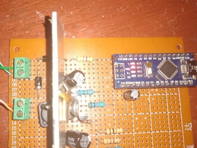
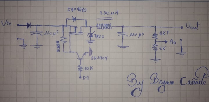
//*************************** Change these values at base of your needs *****************************
#define VoltageR 9.1f //Voltage to regulate

// Setup of mainboard **********************************************************
#define convertion 0.1754f //Conversion factor

// Definition of inputs and outputs ********************
const int uPin = 9; // Control voltage, this is the pin called OC1A
const int x0Pin = A0;  //Voltage at the output of the second integrator

// Variables to signal feedback *************************
float FB = 0; // Feedback signal
float RV = 0; // Reference Voltage
int e = 0;    // Error variable
float Switch_cycle = 0; //Dute Cycle

// Variables to time operations **************************
unsigned long softStart = 500;

void setup() {

  //******************** Set all inputs and outputs **********************************************************
  pinMode(uPin,OUTPUT); // Set pin OC1A as output
  pinMode(13,OUTPUT);   // To indicate the device is operate

  //******************** Set and Clear initial ***************************************************
  digitalWrite(13,LOW); // Start Led Off

  //******************** Calculate all conversions **********************************************************
  RV = (VoltageR*convertion*1024/5); //Convert voltage reference to conversion ADC value

  //******************* Delay before start operation ********************************************************
  SoftStartDelay();

  noInterrupts(); // disable all interrupts while do configure
  // ******************************* Set PWM frecuency **********************************************
  // Freq_PWM = 16Mhz /128 = 125 Khz
  TCCR1A = (1<<COM1A1) | (0<<COM1A0) | (0<<COM1B1) | (0<<COM1B0) | (1<<WGM11) | (0<<WGM10);
  //       COM1A1 = 1  ; COM1A0 = 0 ; COM1B1 = 0  ; COM1B0 = 0  ;         Note: When use a inverted output, you must set COM1A1 & COM1A0, if you use a normal output, you only have to must COM1A1
  //       Clear output OC1A when match happen, Output OC1B disconnected
  TCCR1B = (0<<ICNC1) | (0<<ICES1) | (1<<WGM13) | (1<<WGM12) | (0<<CS12) | (0<<CS11) | (1<<CS10);

  //        ICNC1 & ICES1 are used when Timer had a external signal. Unused in Fast PWM mode
  //        CS12 = 0; CS11 = 0; CS10 = 0; Select no prescaler
  //        WGM13 = 1 ; WGM12 = 1;  WGM11 = 1 ; WGM10 = 0; Select Fast 8 bit PWM with TOP value on ICR1

  ICR1H  = 0x00;  //Set ICR1 register to 80h (#128) MSB = 0x00, LSB = 80h
  ICR1L  = 0x80;  //This value is TOP of the counter. Timer reach to zero when count is equal to it.

  TCNT1H = 0x00; //Reset MSB of the timer
  TCNT1L = 0x00; //Reset LSM of the timer
  OCR1AH = 0x00; //Clear MSB of the match register, unused in Fast PWM 8 bit
  OCR1AL = 0x00; //Set zero to start device off, it register is used to change dute cycle

  // ****************************** Set interrup by timer 2 ******************************************
  // T = (1/16MHz)*(2^8-00)*8 = 128 uS
  TCCR2A = (0<<COM2A1) | (0<<COM2A0) | (0<<COM2B1) | (0<<COM2B0) | (0<<WGM21) | (0<<WGM20);
  //       COM1A1 = 0  ; COM1A0 = 0  ; COM1B1 = 0  ; COM1B0 = 0  ;
  //       OC12A and OC2B both are disconnected

  TCCR2B = (0<<WGM22) | (0<<CS22) | (1<<CS21) | (0<<CS20);
  //        CS22 = 0; CS21 = 1; CS20 = 0; Select prescaler Fosc/8
  //        WGM13 = 0 ; WGM12 = 0;  WGM11 = 0 ; WGM10 = 0; Select Normal Mode operation

  TCNT2 = 0x00; //This register have a pre-load of the timer. However, in this case, it's no have pre-load
  OCR2A = 0x00; //Clear match register. It's unused
  OCR2B = 0x00; //Clear match register. It's unused

  TIMSK2 = (0<<OCIE2B) | (0<<OCIE2A) | (1<<TOIE2); // enable timer2 overflow interrupt
  // ****************************** End of the configurate *******************************************
  interrupts(); // enable all interrupts
}
ISR(TIMER2_OVF_vect) // interrupt service routine
{
  FB = (float)(analogRead(x0Pin));          //Feedback signal

  float k = 0.08;                           //Gain in close loop
  e = RV-FB;                                //Error
  Switch_cycle = Switch_cycle + e*k;        //Control
  if(Switch_cycle<=0)                       //Min duty Cycle = 0
    Switch_cycle = 0;
  if(Switch_cycle>=122)                     //Mx duty Cycle = 95% ;(122/128)*100 = 95.31% real value
    Switch_cycle = 122;
    OCR1AL = (unsigned char)(Switch_cycle); //Write duty cycle
}
void SoftStartDelay() // Delay with interval of 500ms before start regulation
{
  delay(softStart);
  digitalWrite(13,HIGH);
}
void loop() {
  // put your main code here, to run repeatedly:

}


Comments
Please log in or sign up to comment.