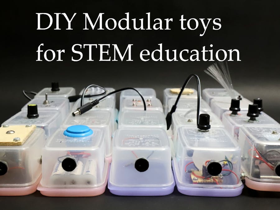
IntroductionRecently, many nodular electronic toy system for STEM education have been released. However, they have some problems. The first is they are expensive. The second is that while they focus on electronics and computer education, they do not emphasize mechanical engineering education with handiwork. Hence we develop a simple and low-cost DIY modular toys for STEM education.
We use 3.6v power source with three nickel-metal hydride batteries. This is because both the LED and 130 motor can be driven at the rated voltage, and there are many ICs that are in the operating range.
The module is basically a single input / output, but there are three types. They are bypass type modules and I / O type modules, and special type modules. The bypass type receives an input voltage and performs its function, and at the same time outputs the input voltage as it is. The I / O type receives the input voltage and performs its function, and outputs the voltage generated to perform its function. Special modules include power supply modules.
In this project page, we introduce "Switch and battery" module, LED module, and Cam and Follower module.
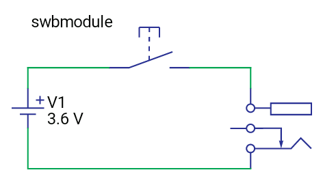
Switch and battery module- Make holes in the container to install the switch, battery box and DC jack. A hole saw is convenient when using a large switch.
- Wire as shown in the circuit diagram below.
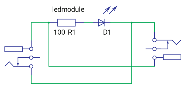
LED module- Make holes in the container to install the two DC jacks.
- Wire as shown in the circuit diagram below. Adjust the resistance value with the LED.
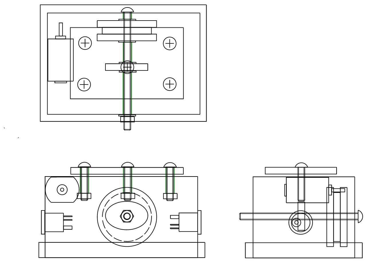
Cam and Follower- Make a follower with a plate, screws and nuts as shown in the figure below, and fit it in the container.
- Mount the motor at the position shown below.
- Assemble the speed change pulley and cam to the shaft in the container using the spacer. The spacer is made by cutting an aluminum pipe. Tighten the nut to fix the pulley and cam.
- Connect the motor and speed change pulley with a rubber band.
- Wire the motor and DC jacks in parallel.


Comments