

Hardware components | ||||||
 |
| × | 1 | |||
 |
| × | 1 | |||
 |
| × | 1 | |||
 |
| × | 1 | |||
 |
| × | 1 | |||
 |
| × | 1 | |||
 |
| × | 1 | |||
Software apps and online services | ||||||
 |
| |||||
In this tutorial, we will integrate Surilli Basic M0 with LED and visualize the blinking action of the LED with the help of a push button. When the push button is pressed, the LED will turn ON and once the push button is released, the LED will turn OFF.
What Is a Push Button?The push button / switch is a component that connects two points in a circuit when you press it.
It is simply a device you can press to connect two pieces of metal together, allowing a current to pass. It’s extremely handy for all sorts of applications.
A push button only has two connections, even though it has four legs.
When the push button is pressed, there will be a connection between all of the legs. The two top and the two bottom legs are connected, but there's no connection between the top and the bottom.
- Surilli Basic M0
- 1 x LED
- 1 x Push button
- 1 x 220 ohm resistor
- 1 x 10k ohm resistor
- Connecting wires
- Bread board
- Arduino IDE software
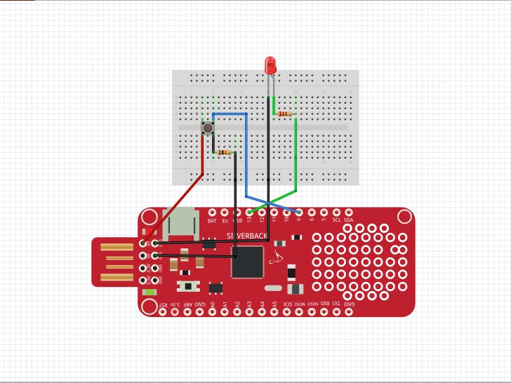
1. Attach your LED to the bread board.
2. Connect the 220 ohm resistor to LED's long leg (+).
3. Connect the wire to the resistor's other leg.
4. Connect the same wire from the resistor to the digital PIN 13 of Surilli Basic M0.
5. Connect another wire to LED's short leg (-) and after that connect the same wire from LED to ground.
6. Attach your push button onto the breadboard.
7. Connect a 10k ohm resistor to the push button leg.
8. Connect a wire to the resistor leg and after that connect the same wire from the resistor to the ground.
9. Connect a wire to the push button's other leg, and after that connect the same wire to USB PIN (5V) of Surilli Basic M0 from the push button.
10. Connect a wire to the push button's top leg, and after that connect the same wire from the push button to PIN 9 of Surilli Basic M0.
Connections between Surilli Basic M0 and LED:
Surilli Basic M0 --> LED
PIN 13 --> long leg (+) of the LED connected to one leg of the 220 ohm resistor along with the second leg of the 220 ohm resistor.
PIN GND --> short leg (-) of the LED.
Connections between Surilli Basic M0 and Push Button:
Surilli Basic M0 --> Push ButtonPIN GND --> One leg of the 10k ohm resistor with the other leg of the 10k ohm resistor connected to the push button.
PIN 5V --> Second leg of the the push button.
PIN 9 --> Third upper leg of the push button.
Set Up Arduino IDE for SurilliMake sure you have selected the right port, board and processor for the Surilli as shown in the picture below and it is programmable (compile and upload “Blink” from File>Examples>Digital>Blink onto your Surilli to check if everything is working fine).
The Circuitry:The circuitry is very simple. It's mostly the programming. Follow the figure below to set up your hardware.
Now you have completed setting up your hardware and Arduino IDE. Copy and paste the Arduino sketch given below into your Arduino IDE and hit upload.
After the Arduino sketch has been uploaded, open the Serial Monitor of your Arduino IDE to actually visualize the blinking action of the LED and the statements "LED OFF" will start appearing on the Serial Monitor depicting that the present status of LED is OFF.
When the push button is pressed with the finger of your hand constantly on the button, the LED will turn ON and at the same time the Serial Monitor will show the command "LED ON" constantly as long as the button is pressed. But as soon as you release your finger from the button, the LED will turn OFF and the Serial Monitor will show a message "LED OFF" constantly as long as the push button is not pressed. This whole process will be explained with the help of 2 live video demonstrations as follows:
Arduino Code:// Set pin numbers
const int ledPin = 13; // Const won't change
const int buttonPin = 9;
// Variables will change
int buttonState = 0; // Variables for reading the pushbutton status
void setup()
{
SerialUSB.begin(9600);
pinMode(ledPin, OUTPUT); // Initialize the LED pin as an output
pinMode(buttonPin, INPUT); // Initialize the pushbutton pin as an output
}
void loop()
{
buttonState = digitalRead(buttonPin); // Read the state of the pushbutton value
if (buttonState == HIGH)
{
// Check if the pushbutton is pressed
// If it is, the buttonState is HIGH
digitalWrite(ledPin, HIGH); // Turn LED on
SerialUSB.println("LED ON");
}
else
{
digitalWrite(ledPin, LOW); // Turn LED off
SerialUSB.println("LED OFF");
}
}
Video 1 (Hardware Running):
Video 2 (Serial Monitor Results):
Play with the program to see how it reacts to different values and logic.
If you make something fun and interesting, do share it with our community.
That’s all for now. If you have any queries, visit surilli.io or contact our support. Stay connected with the Surilli family for more amazing stuff. :-)


_3u05Tpwasz.png?auto=compress%2Cformat&w=40&h=40&fit=fillmax&bg=fff&dpr=2)
Comments
Please log in or sign up to comment.