

Hardware components | ||||||
 |
| × | 1 | |||
 |
| × | 1 | |||
| × | 1 | ||||
 |
| × | 1 | |||
 |
| × | 1 | |||
Software apps and online services | ||||||
 |
| |||||
In this tutorial, we are going to interface an MQ2 Smoke Sensor with Surilli Basic M0 and 16x2 LCD. The changing analog values from the MQ2 Smoke Sensor will be visualized on the 16x2 LCD.
What Is an MQ2 Smoke Sensor?The MQ series of gas sensors use a small heater inside with an electro-chemical sensor. They are sensitive for a range of gasses and are used indoors at room temperature. The MQ-2 Gas Sensor module is useful for gas leakage detecting in home and industry.
The MQ-2 smoke sensor is sensitive to smoke and to the following flammable gases:
- LPG
- Butane
- Propane
- Methane
- Alcohol
- Hydrogen
The resistance of the sensor is different depending on the type of the gas.The smoke sensor has a built-in potentiometer that allows you to adjust the sensor sensitivity according to how accurate you want to detect gas.
A0: Analog pin
D0: Digital pin
GND: Ground pin
VCC: Voltage pin
How Does It Work?The relationship between voltage and gas concentration is the following:
- The greater the gas concentration, the greater the output voltage.
- The lower the gas concentration, the lower the output voltage.
The output can be an analog signal (A0) that can be read with an analog input of the Surilli or a digital output (D0) that can be read with a digital input of the Surilli.
While in this project we will be using analog output.
Note: Don't touch the sensor. It will be very hot.
16x2 LCD:A 16x2 LCD has 2 horizontal rows each comprising of 16 displaying character. This means that a total of 32 characters can be displayed on a 16x2 LCD. An LCD is used in many electronics projects to display the status of the process, voltage levels, sensor values, system health and the list goes on n on.
Pin Numbering:The PIN numbering goes from left to right (1 - 16).
Required Hardware:- Surilli Basic M0
- MQ2 Smoke Sensor
- Connecting wires
- Arduino IDE software
- 16x2 LCD
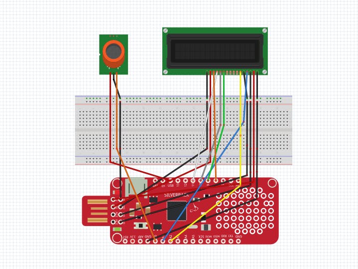
Connections between Surilli Basic M0 and MQ2 Smoke Sensor:
Surilli Basic M0 --> MQ2 Smoke Sensor
- USB Pin (5V) (Surilli Basic M0) --> VCC Pin (MQ2 Smoke Sensor)
- A0 Pin (Surilli Basic M0) --> A0 Pin (MQ2 Smoke Sensor)
- GND Pin (Surilli Basic M0) --> GND Pin (MQ2 Smoke Sensor)
16x2 LCD with Surilli Basic M0:
- -> VSS PIN (LCD) to GND PIN (Surilli Basic M0).
- -> VDD PIN (LCD) to 5V PIN (Surilli Basic M0).
- -> V0 PIN (LCD) to GND PIN (Surilli Basic M0).
- -> RS PIN (LCD) to A1 PIN (Surilli Basic M0).
- -> RW PIN (LCD) to GND PIN (Surilli Basic M0).
- -> E PIN (LCD) to A2 PIN (Surilli Basic M0).
- -> D4 PIN (LCD) to PIN 9 (Surilli Basic M0).
- -> D5 PIN (LCD) to PIN 10 (Surilli Basic M0).
- -> D6 PIN (LCD) to PIN 11 (Surilli Basic M0).
- -> D7 PIN (LCD) to PIN 6 (Surilli Basic M0).
- -> A PIN (LCD) to 5V PIN (Surilli Basic M0).
- -> K PIN (LCD) to GND PIN (Surilli Basic M0).
Make sure you have selected the right port, board and processor for the Surilli as shown in the picture below and it is programmable (compile and upload “Blink” from File>Examples>Digital>Blink onto your Surilli to check if everything is working fine).
STEP 2: The CircuitryThe circuitry is a little complex so we will go through it first. Complete your circuit connections and then move on to the next step. It's mostly the programming. Follow the figure below to set up your hardware.
STEP 3: Upload & Burn Code Onto Surilli
- Now you have completed setting up your hardware and Arduino IDE. Copy and paste the Arduino sketch given below into your Arduino IDE and hit upload.
- After the Arduino Code has been uploaded, the changing Analog values of the MQ2 Smoke Sensor can be viewed on the 16x2 LCD Screen.
#include <LiquidCrystal.h>
int gasPin; // GAS sensor output pin to Surilli Basic M0.
const int rs = A1, en = A2, d4 = 9, d5 = 10, d6 = 11, d7 = 6;
LiquidCrystal lcd(rs, en, d4, d5, d6, d7);
void setup()
{
    lcd.begin(16, 2);
    SerialUSB.begin(115200); // Initialize serial port - 115200 bps
}
void loop()
{
    gasPin = analogRead(0);                      // Read analog input pin A0
    SerialUSB.print("Analog Value=");
    SerialUSB.println(gasPin, DEC);              // Prints the value read
    lcd.setCursor(0,0);
    lcd.print("  Analog Value ");
    lcd.setCursor(0,1);
    lcd.print("   ");
    lcd.print(gasPin,DEC);
    lcd.print("   ");
    delay(1000);                                 // Wait 1000ms for next reading
}
The results obtained in my case is as follows:
Note: You can make the necessary changes / modifications in the Arduino code according to your requirements and see how it reacts to different values and logic.
That’s all for now. If you have any queries, visit surilli.io or contact our support.


Comments
Please log in or sign up to comment.