

Hardware components | ||||||
 |
| × | 1 | |||
 |
| × | 1 | |||
Software apps and online services | ||||||
 |
| |||||
Hello and welcome to Surilli Kit tutorials. Today we are going to interface a simple RGB LED with Surilli GSM.
What is RGB LED?RGB LED means red, blue and green LEDs. RGB LED products combine these three colors to produce over 16 million hues of light. Note that not all colors are possible. Some colors are “outside” the triangle formed by the RGB LEDs. Also, pigment colors such as brown or pink are difficult, or impossible, to achieve.
(Reference to: http://www.lighting.philips.com/main/support/support/faqs/white-light-and-colour/what-does-rgb-led-mean)
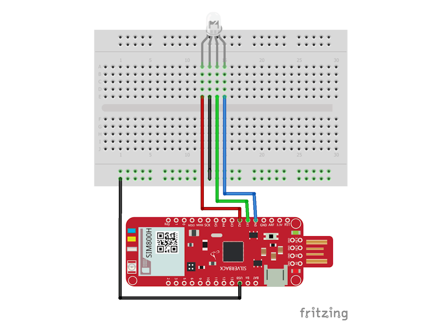
How an RGB LED is made:We will first go through the circuitry which is beginner level.
Circuitry:After you have completed the circuit, open Arduino IDE and move on to the next step
Step 2: Setting up Arduino IDEOpen Arduino IDE and make sure that you have selected the right board & port.
Now copy and paste the Arduino IDE sketch from down below.
NOTE: If you are using this device for the first time you might need to set it up with Arduino IDE first. Visit Getting Started with Surilli GSM and then follow Step 2.
   int redPin= A2;
   int greenPin = A1;
   int bluePin = A0;
   void setup() {
     pinMode(redPin, OUTPUT);
     pinMode(greenPin, OUTPUT);
     pinMode(bluePin, OUTPUT);
   }
   void loop() {
     setColor(255, 0, 0); // Red Color
     delay(1000);
     setColor(0, 255, 0); // Green Color
     delay(1000);
     setColor(0, 0, 255); // Blue Color
     delay(1000);
     setColor(255, 255, 255); // White Color
     delay(1000);
     setColor(170, 0, 255); // Purple Color
     delay(1000);
   }
   void setColor(int redValue, int greenValue, int blueValue) {
     analogWrite(redPin, redValue);
     analogWrite(greenPin, greenValue);
     analogWrite(bluePin, blueValue);
   }
That's it. The LED should start blinking in different colors as soon as the sketch is uploaded.
If you have any queries, feel free to contact us at surilli.io


Comments
Please log in or sign up to comment.