


Hardware components | ||||||
 |
| × | 1 | |||
 |
| × | 1 | |||
 |
| × | 1 | |||
 |
| × | 1 | |||
 |
| × | 1 | |||
 |
| × | 1 | |||
 |
| × | 1 | |||
 |
| × | 1 | |||
 |
| × | 1 | |||
_ztBMuBhMHo.jpg?auto=compress%2Cformat&w=48&h=48&fit=fill&bg=ffffff) |
| × | 1 | |||
Software apps and online services | ||||||
 |
| |||||
Hello readers, hope you are doing fine. In this article, we are going to make an IoT motion detector using NodeMCU and the Blynk application. PIR stands for passive infrared radiation and it generates high output when capturing some movement. We use this in our project for monitoring any movement. You can read the full article on our website.
About the ProjectYou have to provide your network’s SSID and PASSWORD so that the NodeMCU can send data over the internet. Also, specify your authentication tokennumber. When the PIR sensor detects some motion near it the red LED will turn on and the buzzer will start beeping. The green LED will glow in normal conditions.
Open the serial monitor to see the activities and the IP address.
Turn on the PIR sensor by clicking the on button.
If it detects some movement near it or in its range then an alert notification will send by the app on the smartphone.
You have to install the Blynk IoT app and then open the app. Create a new project by clicking on the box whose image is given below.
Then name the project as you want and select NodeMCU as the device. Choose WiFi as the connection type. Tap on create to create your project.
The Blynk app will send a unique authentication code automatically to your given email address. Then press ok to continue.
Now tap on the + symbol to open the widget’s box.
Select a button and a notification widget as shown in the image below. Adjust the position of both widgets on the screen.
Open the configuration settings by tapping on the highlighted button.
Tap on the button and set the pin to V0. You can name the button as an on/off switch. Make it a switch, not a push-button. For notification, do the setting as given in the image below.
Click the marked button so that the app start working and your NodeMCU can link through it.
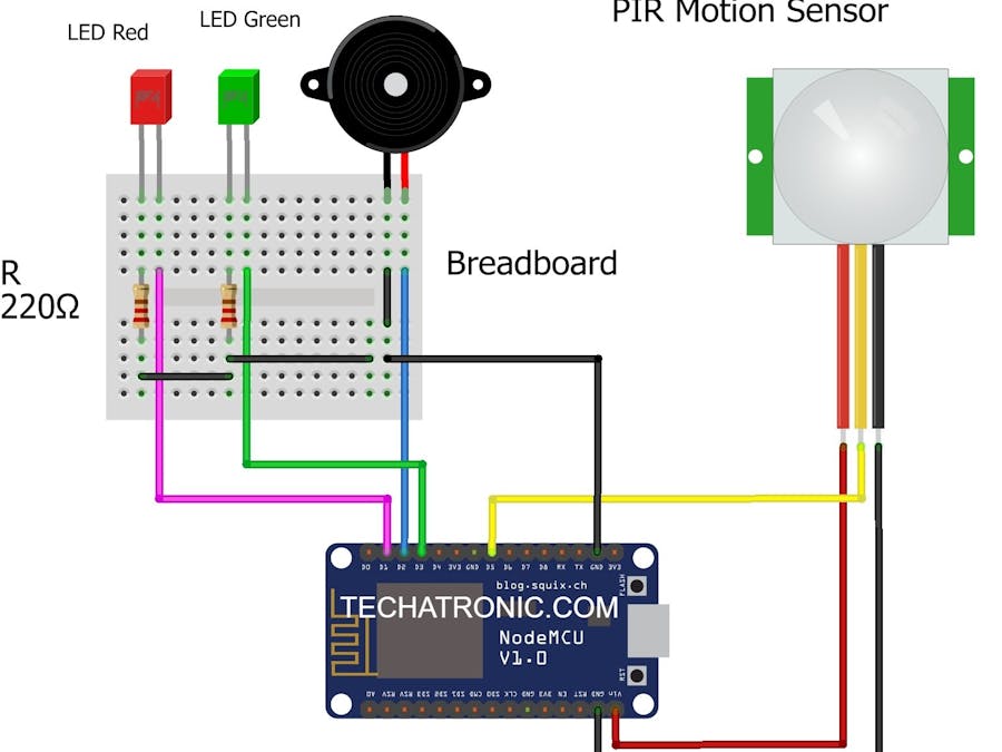
- NodeMCU esp8266 board
- PIR sensor
- LEDs and 220-ohm resistors
- Buzzer
- Breadboard and Jumper wires
- USB cable for uploading the code
- Smartphone with a good internet connection
This is the circuit diagram. Make correct connections according to it.
Code for the ProjectNote: Please upload this code to the NodeMCU.
//TECHATRONIC.COM
// BLYNK LIBRARY
// https://github.com/blynkkk/blynk-library
// ESP8266 LIBRARY
// https://github.com/ekstrand/ESP8266wifi
#define BLYNK_PRINT Serial
#include <ESP8266WiFi.h>
#include <BlynkSimpleEsp8266.h>
char auth[] = "54wl_i7SD0dMWrXBopu0sBt"; //Enter your Blynk application auth token
char ssid[] = "DESKTOP"; //Enter your WIFI name
char pass[] = "asdfghjkl"; //Enter your WIFI passowrd
BlynkTimer timer;
int pinValue = 0;
void setup()
{
Serial.begin(9600);
pinMode(D1, OUTPUT); // RED LED
pinMode(D2, OUTPUT); // BUZZER
pinMode(D3, OUTPUT); // LED GREEN
pinMode(D5, INPUT);  // PIR SENSOR OUTPUT PIN D5
Blynk.begin(auth, ssid, pass);
timer.setInterval(1000L, notifiaction);
}
BLYNK_WRITE(V0)
{
pinValue = param.asInt();
}
void notifiaction()
{
bool sensor = digitalRead(D5); // PIR SENSOR OUTPUT PIN D5
Serial.println(sensor);
if (pinValue == 1)
{
Serial.println("System is ON");
if (sensor == 1)
{
Blynk.notify("WARNING! Please check your security system");
digitalWrite(D1, HIGH); // LED RED ON
digitalWrite(D2, HIGH); // BUZZER ON
digitalWrite(D3, LOW);  // LED GREEN OFF
}
else if (sensor == 0)
{
digitalWrite(D1, LOW); // LED RED OFF
digitalWrite(D2, LOW); // BUZZER OFF
digitalWrite(D3, HIGH); // LED GREEN ON
}
}
else if (pinValue == 0)
{
Serial.println("System is OFF");
digitalWrite(D3, LOW);  // LED GREEN OFF
}
}
void loop() {
Blynk.run();
timer.run();
}
We hope that you like this project and if so then you can also check out the tutorials on Arduino and Raspberry PI written by us.
HAPPY LEARNING!


Comments
Please log in or sign up to comment.