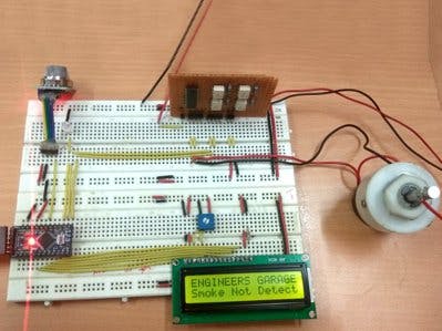
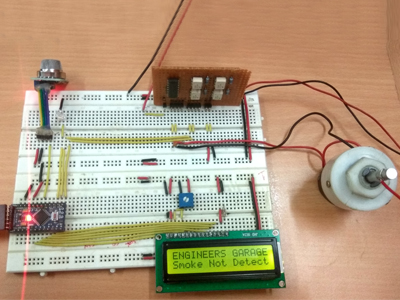
Fire hazards are not uncommon. In order to avoid damage from fire accidents, smoke detectors are installed at high-security places. These smoke detectors detect smoke as the fire breakout and invoke an early alarm. This way, before the fire spreads to other parts of the building, people can be evacuated and countermeasures can be done immediately. In this project also a smoke detector has been designed.
The smoke detector developed in this project not only invokes an alarm but also activates an exhaust fan so that smoke could be removed with immediate action. For the demonstration purpose instead of the actual exhaust fan, a DC motor has been operated in the project. The concentration of smoke is detected by the MQ-6 sensor and displayed on an LCD display. When the concentration of smoke reaches a dangerous level that can be an indication of a fire breakout, a LED indicator is activated.
The project is built on Arduino Pro Mini and MQ-06 gas sensor is used to detect smoke. The MQ6 gas sensor detects the concentration of gas in ppm and outputs analog value which can be converted to digital measure using inbuilt Analog to Digital Convertor of Arduino. The value of the digital measure will be 10-bit long and varies from 0 to 1023. The project allows the user to set the dangerous level for leakage based on the same digital measure. When the value set by the user matches with that of the value detected by the sensor, it invokes the alarm. The MQ6 sensor can be calibrated by interfacing a load resistance of fixed value with the sensor.
The Arduino sketch manages to read sensor data from the MQ-06 gas sensor, compare sensor value, display sensor data on a character LCD, invoke alarm through a LED and operate DC motor in response to intense smoke. The DC motor used as the exhaust is controlled by the L293D motor driver IC.
The circuit is built on Arduino Pro Mini. The MQ-06 gas sensor, LCD display, buzzer and L293D motor driver IC are interfaced with the Arduino board. The circuit is connected in the following manner -
MQ6 Gas Sensor - The MQ6 is a gas sensor module. The module has 4 pins for interfacing of which two pins are VCC and ground, one pin is analog output and one pin is digital pin via a comparator (LM358). The analog output pin of the module is used for detecting concentration level of smoke or gas leakage and interfaced with the A0 analog input pin of the Arduino board. The sensor measures the concentration of leaked gas in ppm according to the following formulae -
Concen = 1036.5*R^-2.392 Where
Concen is the concentration of LPG in ppm
R is the ratio of Rs the resistance of sensor to the R0 which is the resistance at 1000ppm at 20 degree Celsius and 65% humidity
The resistance of the sensor Rs is given by the formulae -
Rs = (1024/ADC_DATA-1)*RL where
Rs is the resistance of the sensor
ADC_DATA is digital reading ranging from 0 to 1023
RL is load resistance ranging from 10K to 40K ohms
Therefore, for a fixed load resistance, the ADC reading is proportional to the concentration of gas in ppm.
In the datasheet, the ratio of concentration to the sensor resistance is given. The graph is done under the normal condition of 20 degree Celsius and 65% humidity. So Rs=R0 for the curve. This way the concentration of gas in ppm becomes equal to ADC reading. The ADC reading will range between 0 and 1023. The analog output pin of the sensor is used for getting the reading. The VCC and Ground pins are connected to the common VCC and ground while the analog output pin is connected to the A0 pin of the Arduino board.
16X2 LCD: The 16X2 LCD display is used to display the value of gas concentration. It is connected to the Arduino board by connecting its data pins to pins 4 to 7 of the Arduino board. The RS and E pins of the LCD are connected to pins 2 and 3 of the Arduino UNO respectively. The RW pin of the LCD is connected to ground.
LED - The LED is connected to invoke an alarm. It is directly interfaced at the pin 12 of the Arduino board. The LED is connected with anode connected to the controller pin and cathode to the ground. For activating the alarm, the LED is set ON by passing HIGH logic at the respective controller pin.
L293D DC Motor Driver IC - The L293D is the motor control driver IC. It has 16 pins with following pin configuration:
Though two DC motors can be controlled using the L293D IC, there is a single DC motor used in the project working an exhaust fan. The DC motor is interfaced between pins 14 and 11 of the motor driver IC.
The L293D IC controls the DC Motors according to the following truth tables:
The pin 4, 5, 13 and 12 of the L293D are grounded while pin 1, 16 and 9 are connected to 5V DC and pin 8 is connected to 12V DC. The pins 15 and 10 of the motor driver IC are connected to pins 10 and 11 of the Arduino board via optocouplers. The optocouplers save the Arduino board from any back current from the motor driver IC.
Power Supply - In the circuit, Arduino and other ICs need a 5V regulated DC for their operation while motor driver IC also needs 12V DC. An 18V battery is used as the primary source of power. The supply from the battery is regulated to 5V and 12V using 7805 and 7812 ICs. The pin 1 of both the voltage regulator ICs is connected to the anode of the battery and pin 2 of both ICs is connected to ground. The respective voltage outputs are drawn from pin 3 of the respective voltage regulator ICs. A LED along with a 10K Ω pull-up resistor is also connected between common ground and output pin to get a visual hint of supply continuity.
How the circuit works -Arduino Based Smoke Detector Circuit Working
When the device is powered on, the Arduino initializes the sensor module and the LCD display. It starts reading data from the MQ-06 sensor. The data is read from the analog output pin of the sensor. The read data is in the form of an analog voltage which is digitized using inbuilt ADC channel. The ADC channels on the Arduino board are 10-bit long so the digitized reading varies from 0 to 1023. On calibration, the ADC reading is directly proportional by a factor of one to the concentration of smoke in PPM. The reading is stored in a variable and displayed on the LCD display.
The reading is compared with a calibrated threshold representing the dangerous level of smoke detection. If the concentration of smoke in PPM exceeds the threshold value, the Arduino board activates the alarm indicator in the form of LED by sending a HIGH pulse at the respective controller pin and activates the DC motor used as exhaust. Otherwise, until the concentration of smoke in PPM is not beyond the dangerous limit, the LED is kept OFF by passing a LOW at the respective controller pin and motor is kept in stop condition by passing LOW at the pins controlling motor input signals.
Check out the project code to learn how the portable Arduino board reads data from the MQ-06 sensor, store sensor data, display it on the LCD screen, compare it with a threshold value and activate motor as well as LED indicator on detecting the dangerous level of smoke concentration.
Programming Guide -The liquidCrystal.h is imported to handle LCD and an object of LCD type with controller pins assigned to it is instantiated. The variables denoting circuit connections of LED, the analog output pin of the gas sensor and motor driver IC are declared and assigned controller pins.
#include <LiquidCrystal.h>
LiquidCrystal lcd(2, 3, 4, 5, 6, 7);
int led = 12;
int Gassensor = A0;
int motor11 = 10;
int motor12 = 11;
The setup() function is called which runs for once and in which the pins connected to motor driver inputs and LED are set to digital output using pinMode() function and the baud rate for serial communication with the LCD is set to 9600 baud per second using begin() method on the serial object. The LCD object is initialized to 16X2 character mode and some initial messages are displayed on it.
void setup()
{
pinMode(motor11, OUTPUT);
pinMode(motor12, OUTPUT);
pinMode(led, OUTPUT);
Serial.begin(9600);
lcd.begin(16, 2);
lcd.print("ENGINEERS GARAGE");
lcd.setCursor(0, 1);
}
The loop() function is called which iterates infinitely. In the loop() function, the sensor value is read using analogRead() function and stored in a variable. The value is printed on LCD display and compared with 200 PPM concentration level. If it is less than 200, the motor is kept off and LED indicator is also kept OFF. A message showing no smoke detected is displayed on the LCD. If the concentration of smoke is more than 400 PPM, the motor is activated to rotate clock-wise and LED indicator is switched ON. A message showing smoke detected is displayed on the LCD.
The complete Arduino code for Smoke Detector Project can be found in the source code section.
.


Comments
Please log in or sign up to comment.