Current Cost make a range of electricity power meters, including the EnviR that wirelessly connects to a clamp meter for the house supply, these can be picked up relatively cheaply on eBay as well as individual IAM modules for appliances. The Envir displays the power usage and trends on an LCD screen which is nice, however getting this data to the internet for long term monitoring and potentially acting on is a different matter.
The Envir doesn't have built in Internet connectivity but Current Cost do sell a NetSmart module that plugs into the Envir, however this only sends the data to CurrentCosts own platform (my.currentcost.com), which leaves a lot to be desired, what I wanted was some way to get my electricity usage data to my preferred IoT platform (Tinamous.com - see my profile for one of the reasons why :-) ), and to use the power of the Photon to do some processing before sending the data.
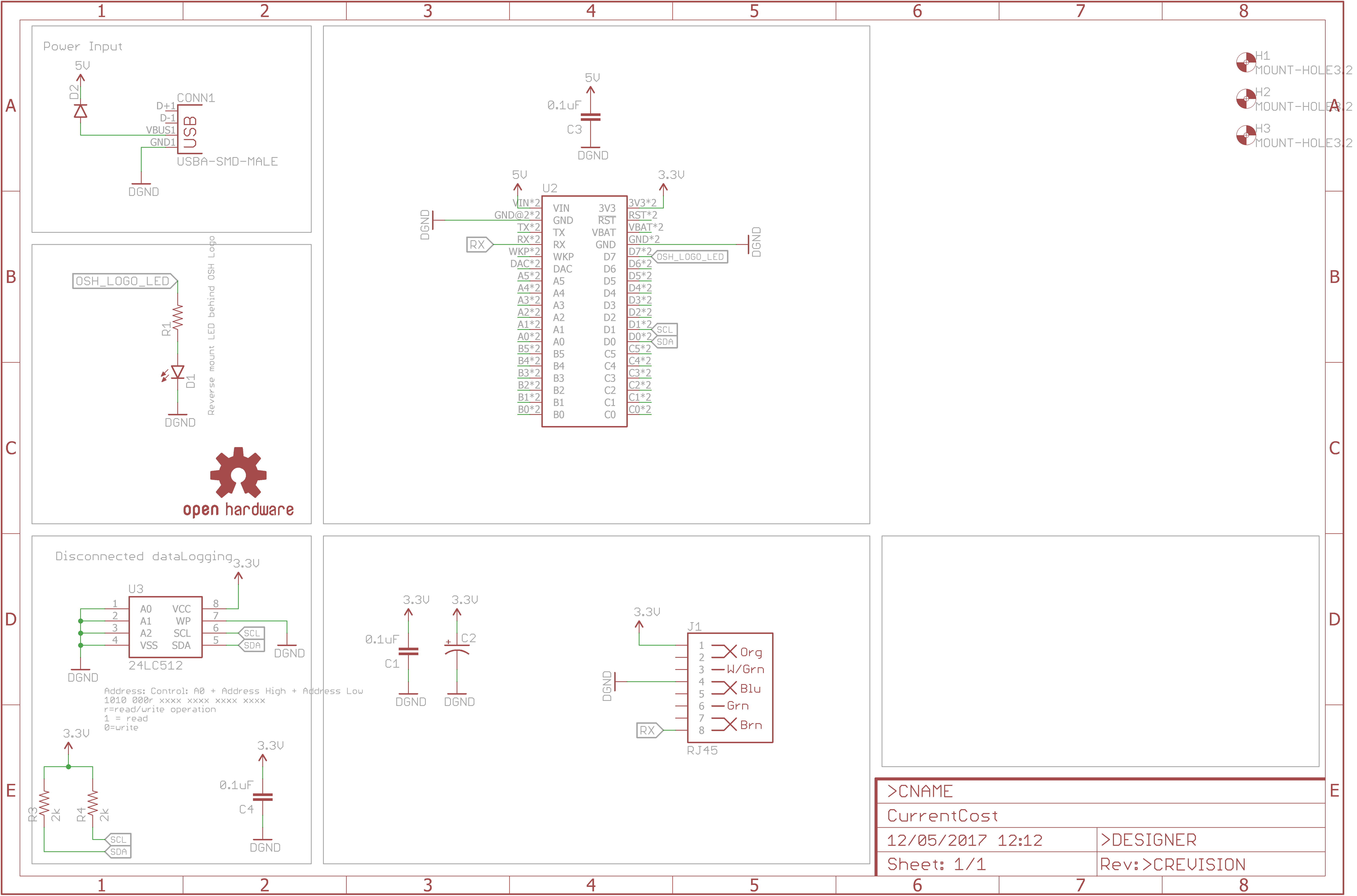
After a little digging I discovered the Currrent Cost Envir monitor uses a simple serial interface via the RJ45 jack, this can also be used to power the Envir unit as well. Just add a Photon (or Electron), a RJ45 lead and some code....
The RJ45 pinout is nice and simple:
- Pin 1 Vcc supply (3v3 on Photon)
- Pin 4 GND (Gnd on Photon)
- Pin 7 EnviR Rx (Not connected).
- Pin 8 EnviR Tx (Rx on Photon)
My initial prototype was with a breadboard and RJ45 breakout board.
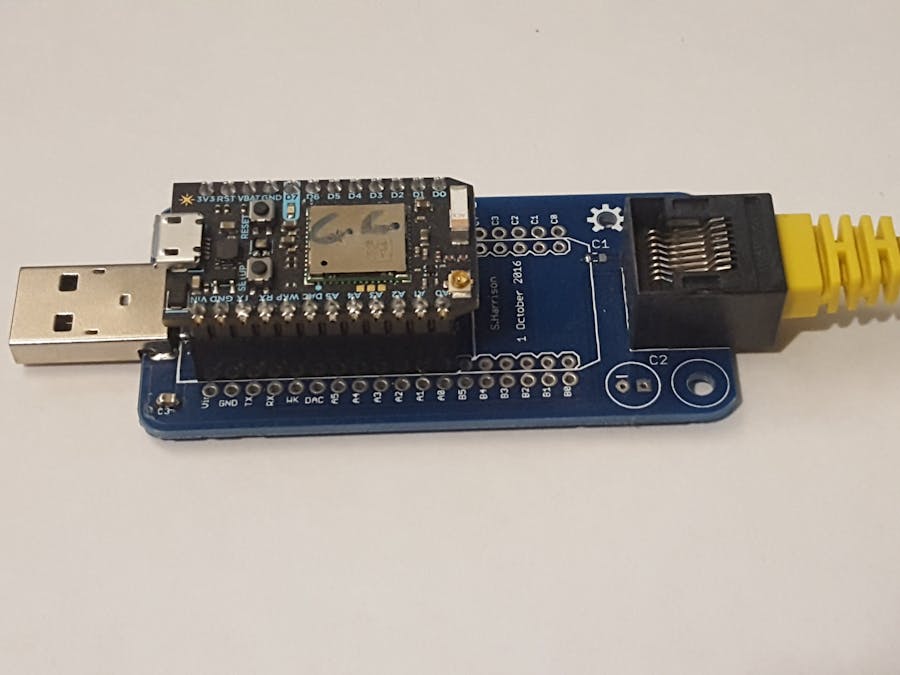
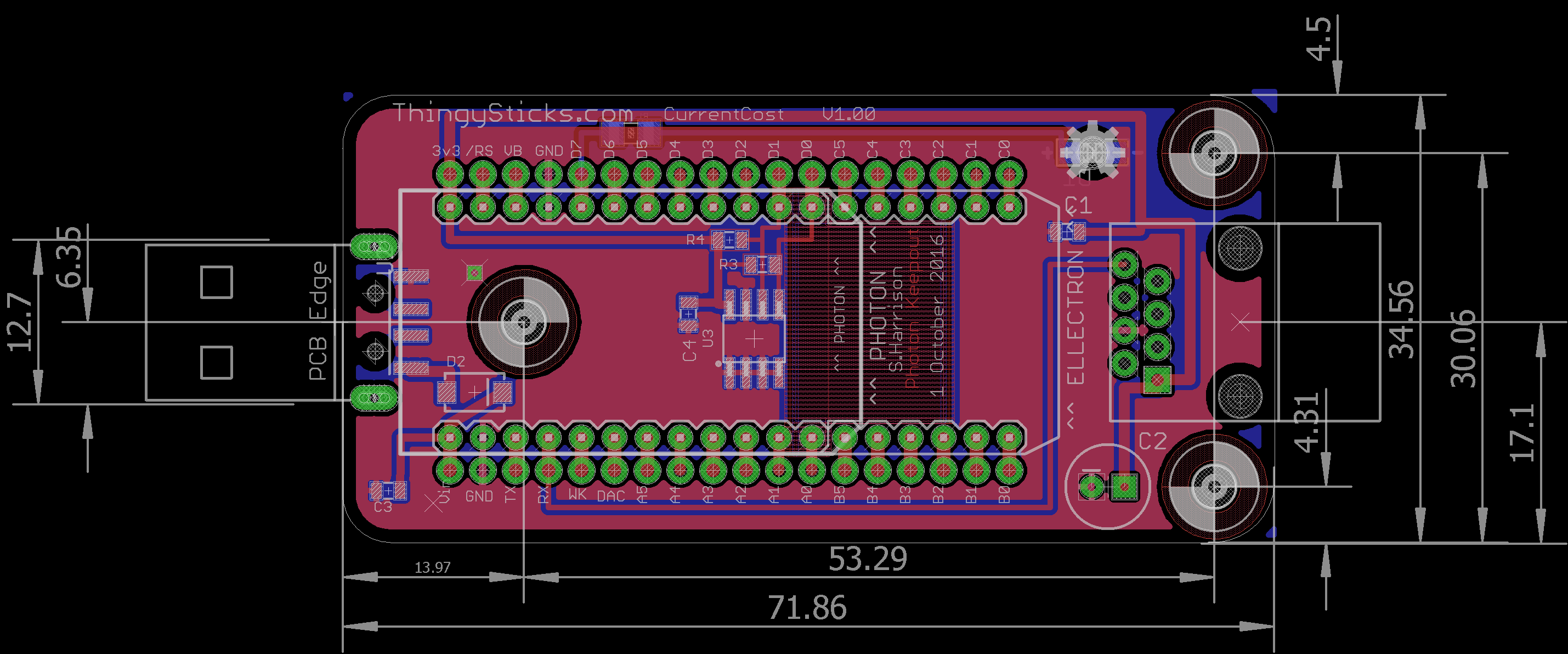
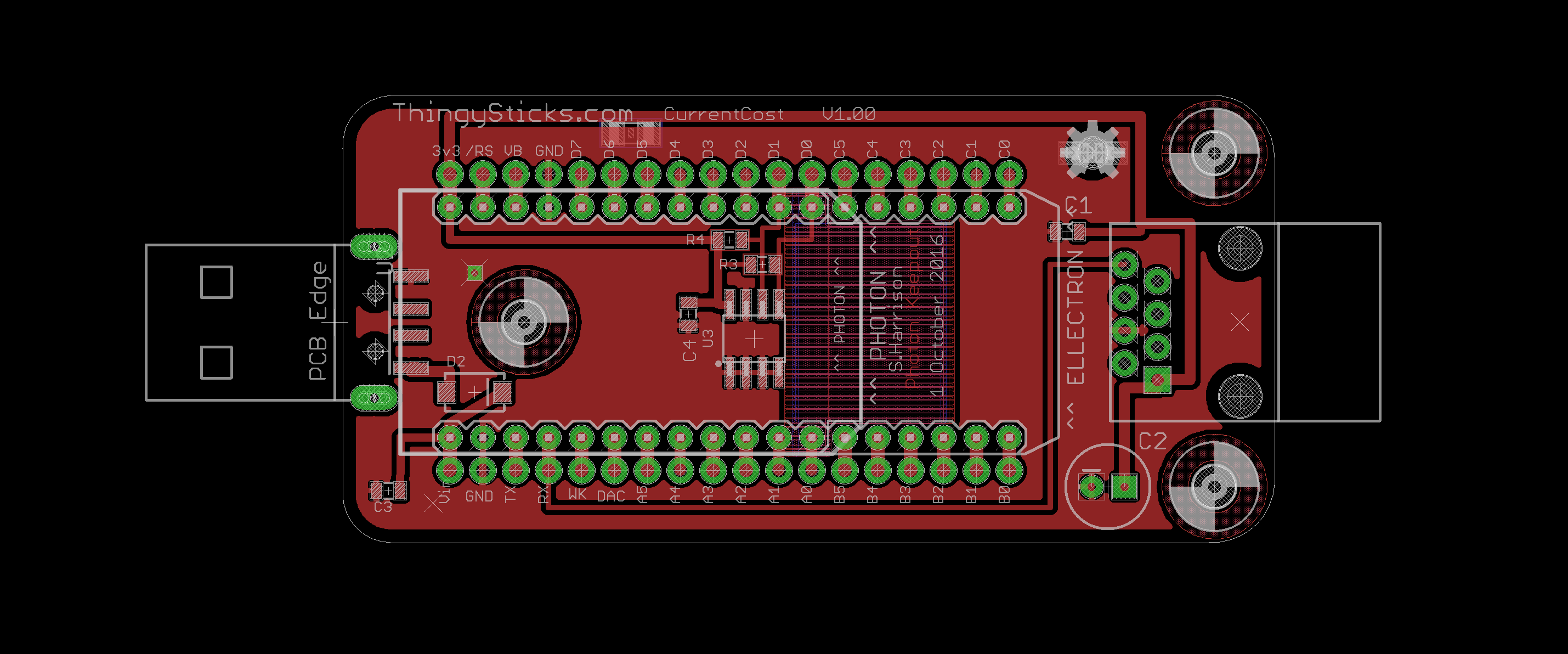
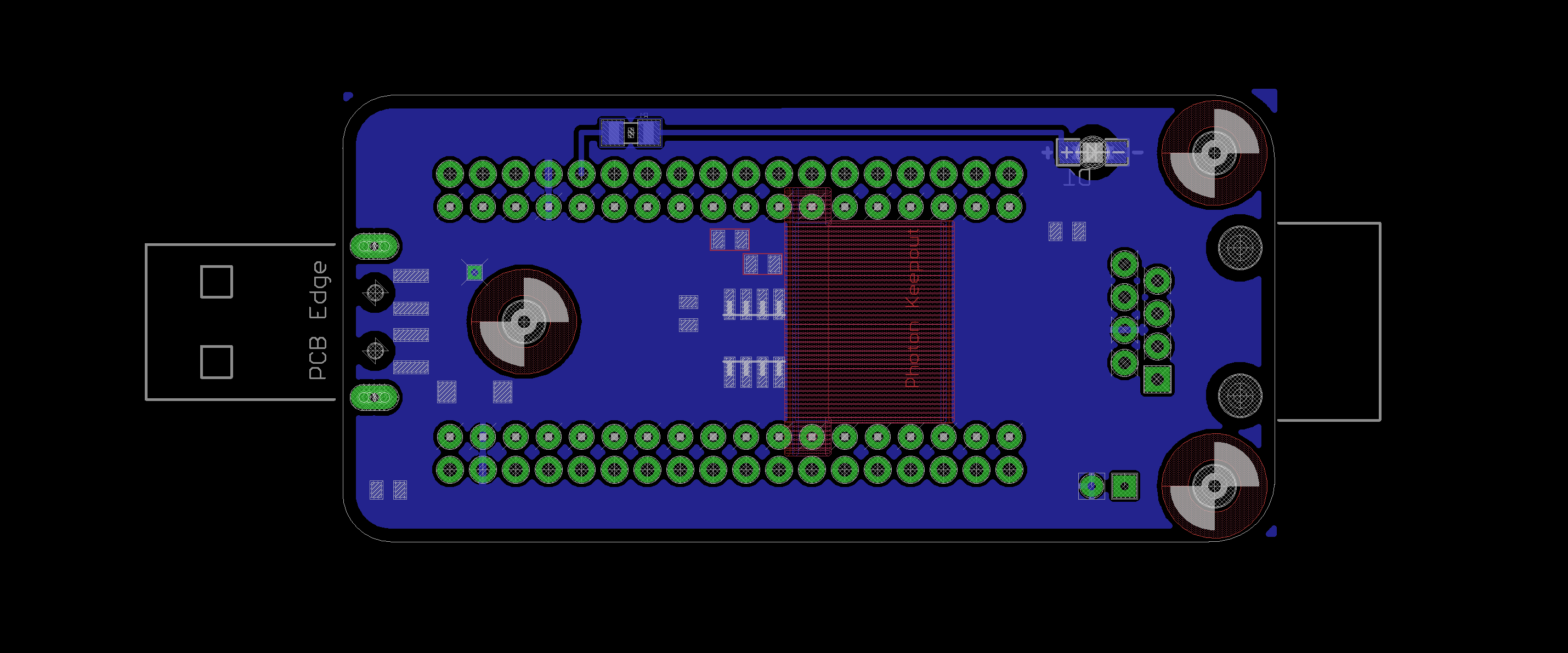
This worked well but it's a little messy for a long term solution, so I threw together a PCB with a USB A plug on one end so it can be plugged directly into a USB power pack or hub. I added space for an EEPROM for additional storage should the device not have internet access and used the footprint for the Electron so either Photon or Electron can be used to monitor power usage.
In the end I've left most of the PCB unpopulated, just the RJ45 socket, Photon and USB A Plug.
I made a little box for it and plugged the PCB into a USB hub for power
For remote power monitoring (i.e. a farm building) the Photon can be swapped out for an Electron and the data transmitted over the cell network, however the current software is fairly noisy (sending every 5 seconds) so a bit more intelligence could be added to just send occasional power consumption and cumulative power.
Solar Power MonitoringUsing the Current Cost clamp, the inverter AC output power could be measured with this system to give an indication of the power generated from a solar array.
ConstructionConstructions is really simple, grab the Eagle brd file and submit it to OSHPark to have a PCB made, you'll get 3 nice purple PCBs for $20, solder on a USB A Plug and RH45 socket, add headers for the Photon (or solder it directly to the PCB if you prefer). Grab a RJ45 cable, I used a flat flexible one as that was easier, you don't need the twisted pairs, and connect the Current Cost Envir to your PCB.
FirmwareBeing a software developer I've naturally over complicated the firmware..
During setup the USB serial port is enable for debugging and Serial1, the hardware serial port is set to 57, 600 baud for the current cost. a few buffers are reserved for reading and publishing messages and control of the onboard RGB led is taken for additional debugging.
void setup()
{
   // USB
   Serial.begin(57600);
   // via TX/RX pins for current cost.
   Serial1.begin(57600);
   // Reserve space in the buffers.
   buffer.reserve(100);
   messageBuffer.reserve(512);
   json.reserve(256);
   // LED indication of RX data
   pinMode(statusLed, OUTPUT);
   digitalWrite(statusLed, LOW);
   // RGB indication of publish.
   RGB.control(true);
   RGB.color(255, 255, 255);
   // Set-up the appliances
   setupAppliances();
   Particle.publish("Current Cost Monitor V0.08");
}
The Envir publishes xml messages along the lines of:
<msg>
  <src>CC128-v1.29</src>
  <dsb>01579</dsb>
  <time>19:25:29</time>
  <tmpr>23.7</tmpr>
  <sensor>2</sensor>
  <id>02927</id>
  <type>1</type>
  <ch1>
    <watts>00506</watts>
  </ch1>
</msg>
Here we see that channel 1 of sensor 2 is measuring 506 watts of power.
In the loop function we keep a buffer of the message received as the full message may take a few loops to be received, then when we have both opening and closing elements (<msg>...</msg>) the message is processed.
void loop() {
   // move the messages from the serial receive
   // to the main message buffer to be processed here.
   messageBuffer+=buffer;
   buffer = "";

   // Look for "</msg>" as the indication the end of the message has been read.
   // xml end terminator found.
   int messageStartPosition = messageBuffer.indexOf("<msg>");
   int messageTerminatorPosition = messageBuffer.indexOf("</msg>");
   if (messageStartPosition>=0 && messageTerminatorPosition>0) {
       // This ignores the > at the end, that's left in the buffer
       // to combines with future mesages.
       messageTerminatorPosition = messageTerminatorPosition + 6;
       // Extract the message.
       String message = messageBuffer.substring(messageStartPosition, messageTerminatorPosition);
       // Remove the string we are processing and anything we're ignoring before it.
       messageBuffer.remove(0, messageTerminatorPosition);
       // ensure buffer contains the start terminator.
       // Ensure that we have at-least <tmpr> start element
       // don't care about anything before that though.
       if (message.indexOf("tmpr") > -1) {
           processPower(message);
       } else if (message.indexOf("<hist>")) {
           processHistory(message);
       } else {
           Serial.println("Unknown message: " + message);
       }
   }

   ...
}
The processPower function extracts the data from this message, updates the stored sensor state and checks the appliances array to see if the power usage matches that of a known appliance.
void processPower(String message) {
   Serial.println("Processing Power: " + message);
   RGB.color(00, 255, 00);
   temperature = extractTemperature(message);
   int sensorId = getSensor(message);
   // Sensor may have upto 3 Channes of data.
   // but for now, just use channel 1.
   int powerNow = extractChannelData(message, 1);
   // -1 indicates channel data not found.
   if (powerNow >= 0) {
       updateSensorState(sensorId, powerNow);
       checkAppliances(sensorId);
   }
}
Every 5ish seconds the values recorded for the sensors are published
// Publish the sensor values (power)
void publishSensorsJson() {
   // Build up the json string.
   bool hasData = false;
   json = "{'t': '" + temperature + "' ";

   for (int sensorId = 0; sensorId < MAX_SENSORS; sensorId ++) {
       SensorState sensorState = sensorStates[sensorId];
       // Only publish the sensor valur if it has a new value since last publish.
       if (!sensorState.published) {
           hasData = true;
           json.concat(",'S" + String(sensorId) + "':'" + String(sensorState.powerWatts) + "' ");
           json.concat(",'D" + String(sensorId) + "':'" + String(sensorState.deltaPower) + "' ");
           sensorStates[sensorId].published = true;
       }
   }
   json.concat("}");
   // Only publish if we have new (unpublished) measurements
   if (hasData) {
       Serial.println("json: " + json);
       Particle.publish("json", json);
   }
}
This creates a json message with with keys such as "S1" and "D1" for sensor 1, representing power and delta power (the change in power from the previous measurement). The json will look like:
{'t': '27.6' ,'S0':'1259' ,'D0':'-8' ,'S2':'375' ,'D2':'17' ,'S5':'0' ,'D5':'0' ,'S6':'203' ,'D6':'-16' }
This is then published using the Particle.publish method with the key "json" which allows Tinamous to pick up the measurements and process them.
I've also defined a few appliances that the firmware knows about, such as the electric shower, this only shows on the whole house power, but it has a distinct power consumption, so when a change in power is recorded by the power usage (between 7 and 8KW), the shower state is updated. I've also defined dishWasher, washingMachine and kettle. These will obviously be different for different installations.
void setupAppliances() {
  ....

   // Shower
   ApplianceTrigger shower = ApplianceTrigger();
   shower.name = "Shower";
   shower.sensorId = 0; // House sensor
   shower.triggerLevelLower = 7000;
   shower.triggerLevelUpper = 8000;
   shower.lastTriggeredAt = 0;
   shower.resetAfter = 0;
   // allow upto 30 minutes for a shower before
   // forcing a reset.
   shower.reTriggerDelaySeconds = 30 * 60;
   shower.isTriggered = false;
   shower.triggerCount = 0;
   shower.clearOnPower = true;
   //
   applianceTriggers[0] = dishWasher;
   applianceTriggers[1] = washingMachine;
   applianceTriggers[2] = kettle;
   applianceTriggers[3] = shower;
}
It would be fairly pointless to make all this without some way to visualise the data, this is where Tinamous.com comes in.
I added a ParticleBot from the bots page, this connects to the Particle device cloud and automatically imports all my Particle devices and assigns Tinamous devices to represent them, it then watches for events from the devices and parses well known events (such as the "json" event we published earlier).
I edited the device to set the primary field as the house power and the "Not Reporting After" to 5 minutes to give me a fairly quick warning if my code on the Photon has crashed....
Tinamous will generate the fields automatically once data is published from the device, here we can see the fields, but I've edited the friendly name and units as "S1" isn't to helpful! I've also applied tags to aid grouping and to help with a dashboard.
On the device page we can drill into the charts, below is my total (house) power usage for the 29 June. A spike at midday when I took a shower, and the air conditioner running from about 3pm (this week we are experiencing summer in the UK!).
I also have IAM's (individual appliance monitors) for a few things, including my computer, here we can see the power consumption when on standby and when running:
A look at the "Particle" section of the device page and we can see the data events coming in...
And naturally a real-time dashboard for seeing where all my electricity is going!
I've not connected the tx pin of the Photon to the EnviR, I didn't think this was needed, however the result of this is the time is not set correctly on the EnviR.
This was a nice and simple project to make, the hardest part turned out to be getting a photo of the EnviR LCD screen and trying to find something that would fit nicely into the Hackster project photo box!






Comments
Please log in or sign up to comment.