My garage has no mains electricity or WiFi and so I use an old car battery for power and LED lighting, I'd like to know when the battery is getting flat, or if the door is open without having to go out to the garage.
I'm sure many remote/agricultural buildings have similar problems where it's not feasible to run a mains supply and so they rely on battery power, maybe for powering the electric fences, small low power pumps to keep a leak from flooding or simple occasional lighting.
This project provides a way to monitor the battery level and power usage, along with sensor inputs and provide switchable outputs as well as a 5v USB power socket.
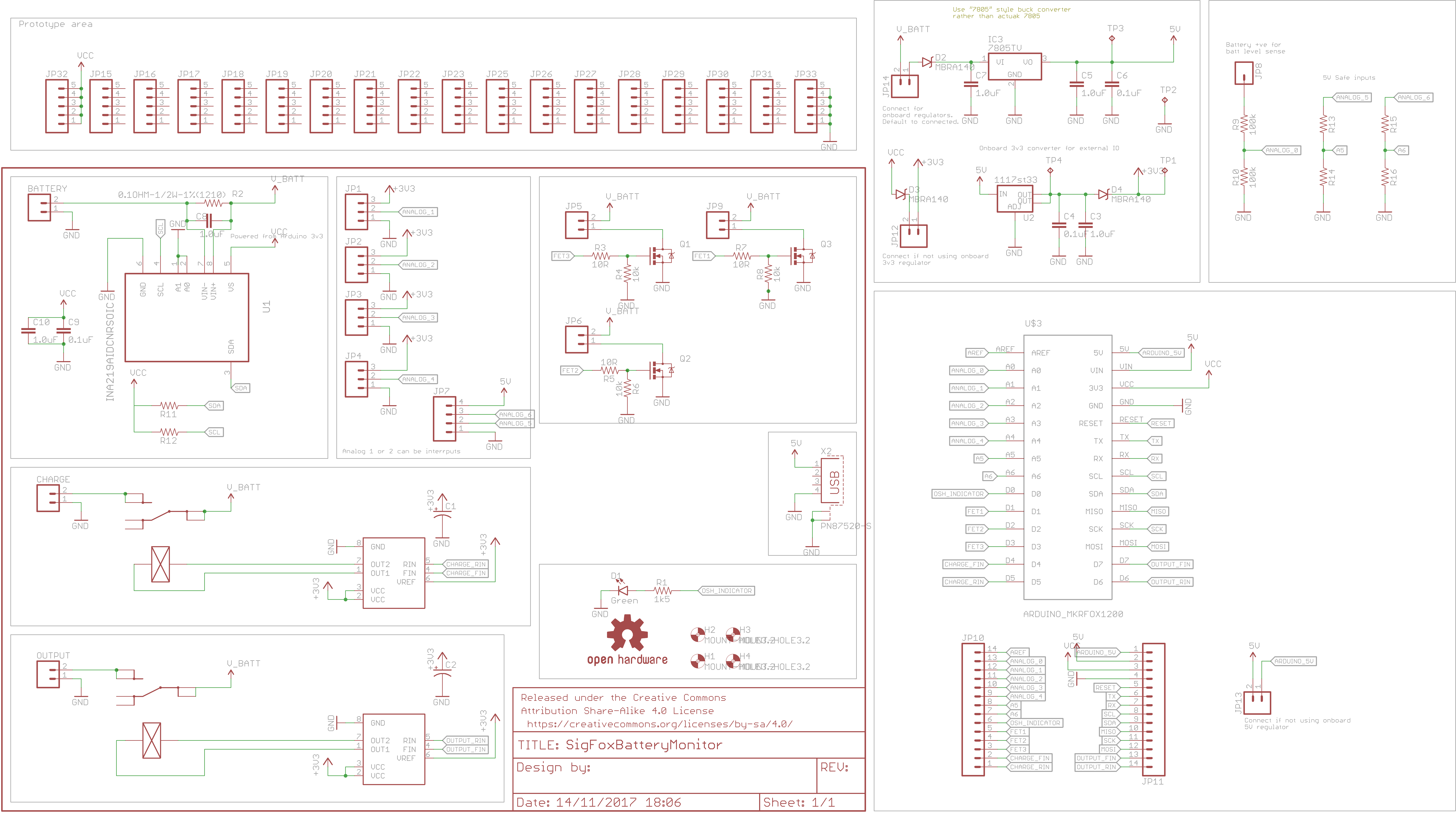
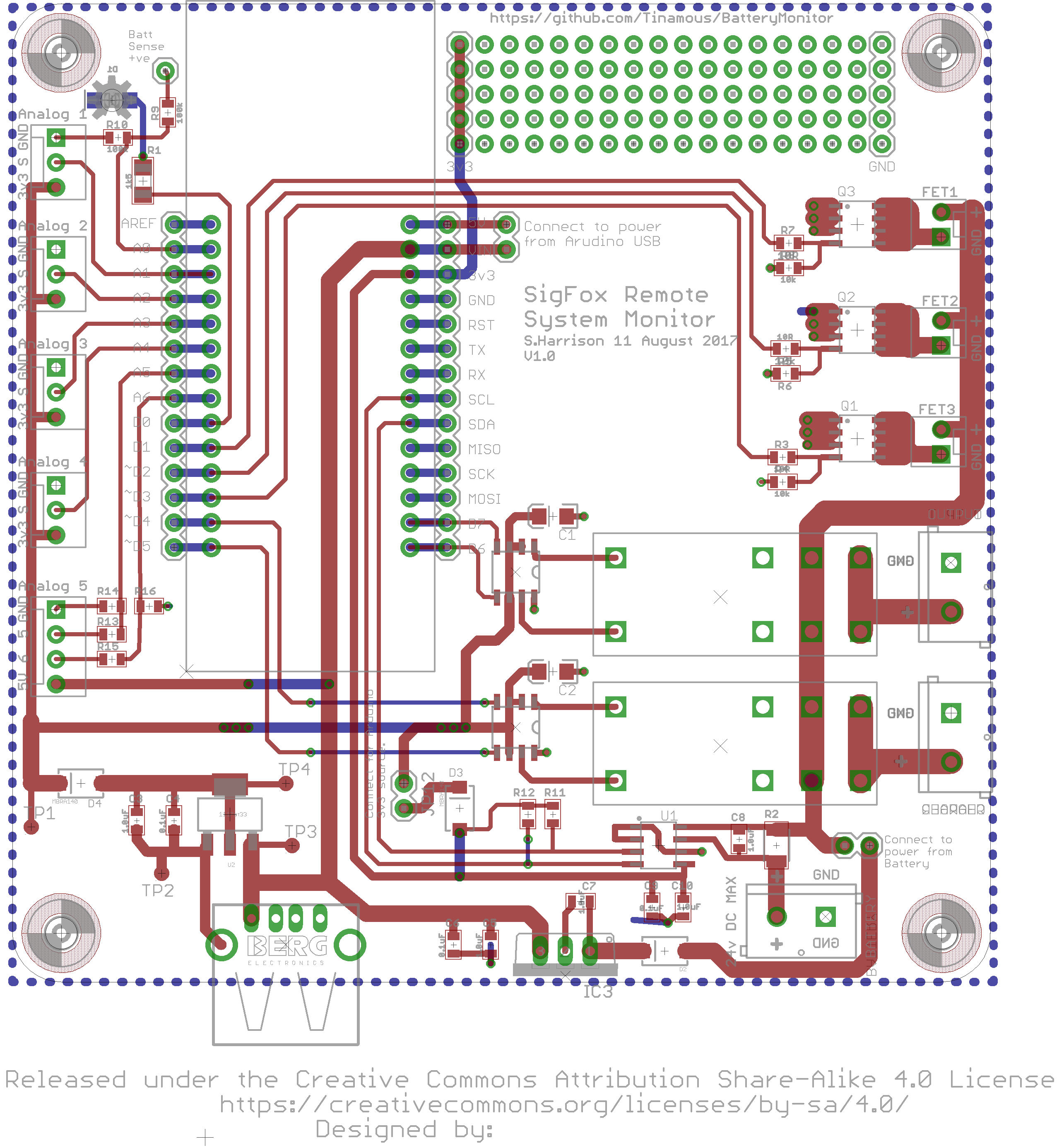
Construction:- The battery (12 or 24V lead acid) is connected through the lower 2 pin terminal block, leading to a 0R1 ohm resistor connected to a INA219 to monitor voltage and current flow (in and out of the battery) and then to the relays and FETs above.
- Two latching relays are used for a power out and/or charge (solar) input on the right and above that 3 optional N-Channel FET controlled outputs.
- An Arduino MKR FOX 1200 at the heart allows for low power Sigfox wireless communications and monitoring of the system.
- On the left a series of analog or digital inputs can be used with things like motion sensors, push button switches, door contact switches, water level sensors etc.
- Analog 1-4 connectors have both 3v3 and GND as well as the signal pin (A1-A4 on the Arduino.
- Analog 5 (4 pin connector) has 5V power and the inputs are via potential dividers to allow for a 5V input - this can be useful for hall effect flow sensors that need a bit more juice than 3v3 and connects to A5 and A6.
- Bottom left is a 5V USB power connector (Allows for charging of my phone or other equipment when in the garage).
- An on-board 5V and 3v3 regulator convert the battery voltage to 5V for USB power and 3v3 for the Arduino. Note that most of the system can run powered from the Arduinos 3v3 if this is preferred. The Arduino could also drop back to its own battery input if needed whilst still measuring the main battery/current and other sensors.
- Top right is a small prototyping area to allow a little customisation.
- All the pins of the Arduino are brought out to a second row of connectors for easy prototyping.
- The various power rails have diodes and optional jumpers to allow for powering from the Arduino or battery (or both).
The chart below shows the battery voltage over the last 28 days, you can clearly see when the charger was connected. A peak at the tables below the chart also shows current consumption ( I disabled it on the chart to keep it clearer).
The Arduino monitors the battery voltage and current flow, this is reported back via the Sigfox cloud to Tinamous where it can be monitored and notifications send on low voltage. Sigfox allows for a maximum of 140 messages a day so the measurements are reported every 15 minutes.
At present the charge input is switched off with every Sigfox uplink, this allows the system to determine how much power is being used by the consumer (otherwise charger current may be drawn as well) and the battery voltage without the charge voltage applied. However this means operation of the relay which will lead to increased battery discharge over time.
The Adafruit library for the INA219 is used for the Arduino to monitor the INA219 and the resistor.
Power Control and SensorLatching relays are used for output/charge control as they draw no power in either state once set. To set the relay in either state the coil polarity is changed, this is achieved using a H-Bridge driver (BD6211F) and two outputs from the Arduino. A double high or double low output has no effect on the relay, and a high & low or low & high output puts the relay into the desired state. Then both outputs are set to low to remove power from the relay.
The BD6211F H-Bridge driver is intended to drive motors, hence the inputs are for forward and reverse (RIN, FIN) which may be a little confusing for a relay!
Unfortunately I used D6 for one of the relay pins which is also used by the Sigfox chip as an indicator when in debug mode, this results in the output relay playing some interesting tunes when transmitting Sigfox data.
Whilst the relays are marked Charge and Output both could be used for outputs allowing one to be switched off as the battery gets low to ensure a more critical circuit remains powered.
The N-Channel FETs can be driven with a simple high/low digital pin, however these do not latch so once the Arduino is placed in low power state they will revert to off.
This project uses Sigfox for connectivity, this is ideal for this solution as it gives us low power and long range and is handily build into the Arduino MKR FOX 1200.
Data sent to the Sigfox cloud is limited to 12 bytes, which is plenty of space as the device only needs to transmits status, voltage, current and temperature. The data structure is:
typedef struct __attribute__ ((packed)) sigfox_message {
 uint8_t status;     // status::uint:8 -> Split to 8 bits
 uint8_t version;    // version::uint:8
 int16_t temperature; // temperature::int:16:little-endian
 int16_t current;    // current::int:16:little-endian (e.g. 1159 mA -> 0487 but stored as 8704)
 uint16_t voltage;   // voltage::uint:16:little-endian
 int16_t currentOffCharge;   // currentOffCharge::int:16:little-endian
 uint16_t voltageOffCharge;   // voltageOffCharge::uint:16:little-endian
} SigfoxMessage;
At the Sigfox cloud we define a custom callback with a custom payload configuration to convert this to json properties to send to Tinamous.
The configuration used is:
status::uint:8 version::uint:8 temperature::int:8 current::int:16:little-endian voltage::uint:16:little-endian humidity::int:16:little-endian light::uint:8 light2::uint:8 lastStatus::uint:8
So for example the first byte parsed is read as a unsigned integer of 8 bits and is put into the customData#status property. Next version is read, then temperature and following that current, this is a little more interesting in that it reads 16 bits (2 bytes) and converts it using the little-endian format (least significant digit is read first, then most), so a packet with 0x0A 0x1B bytes would result in a current property of 0x1B0A (6922), voltage, humidity, light and lastStatus are then read in similar style.
Current is represented in milliamps inside the signed 16 bit integer which allows for +/-32A at 1mA resolution, more than ample given I selected the wrong resistor package which limits it to 2A!
Voltage is held as a float (e.g. 12.34) but is converted via a x100 factor into a 16 bit unsigned integer (i.e. 1234) when sent to Sigfox, this is more than enough precision for battery monitoring and keeps the data structure small.
The first byte (status) is composed of a series of bit flags:
// B7: Battery Flat
// B6: Charge Relay state
// B5: Charging
// B4: Reserved
// B3: Output relay state
// B2: Fet 1 state
// B1: Fet 2 state
// B0: Fet 3 state
This allows a single byte to convey the state of the outputs of the system.
Sigfox Cloud:On first use the Arduino needs to be activated at the Sigfox cloud, this is very easy but you need to ID and PAC from the Arduino. These are printed out via the serial port when the system is first powered up.
With ID and PAC in hand head on over to https://backend.sigfox.com/activate to activate the device following the wizard.
Once activated the device and device type are available through the Sigfox backend, we then set-up a custom callback to push the data to Tinamous.
It's important to note that the Arduino uses little-endian format for multi-byte words but Sigfox default to big-endian this needs to be specified in the call back configuration.
I added a Sigfox Bot to my Tinamous account, this enables the callback to push data into my Tinamous account. Each Sigfox device gets it's own Tinamous device to represent it.
For more information on connecting Sigfox to Tinamous see my other "Get Your Sigfox On" project for instructions on how to do this.
Tinamous will automatically add fields to a device when measurements are push in based on the fields specified in the callback. However, these tend to have unfriendly field names, no units and Tinamous has no way to know that voltage is actually 1/100 of the value that is pushed in.
This is easily fixed by editing the device and updating the field definitions.
For voltage we need to go one step further into the Advanced options and apply a calibration, I also set a working range on this as well which means I can set-up notifications if the battery voltage is out of range.
I applied a calibration of y = 0.01x + 0 (where x is the reported value and y is the actual resultant voltage), so a value of 1345 translates to a voltage of 13.45V.
Next I created a dashboard so I could get a quick overview of the battery state, current consumption, temperature and the Sigfox signal strength. This is currently in sitting my house, sadly it's certainly not 17°C in the garage!.
This project hasn't made it out to the garage just yet (pending some wood for the wall and time to fit it), however it's been happily running from a car battery for the last month and has performed well (and not totally flattered the battery yet!).
Low power mode is not implemented at this time as it messes up the serial port and I wanted to iron out a few bugs. Current consumption is about 13mA in its present state, some of this is down to the 5v regulator. At this rate the 70AH car battery would last about 220 days powering only the monitor which isn't ideal, but if a system had solar charging and needed continuous sensor monitoring and control this would be fine.
Downlink from Sigfox isn't yet configured, this could be used to control the relays and/or FETs but it's not needed at present for my garage.
Yes, I spelt Sigfox wrong on the PCB silk screen!
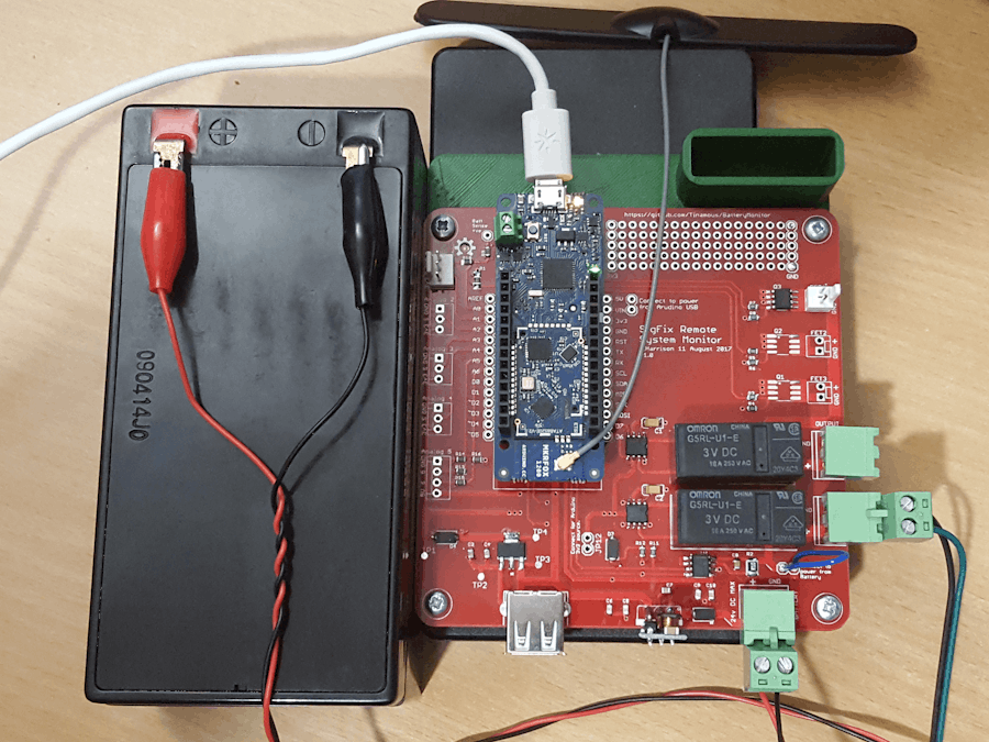
The current test set-up ready to be moved to the garage:


Comments
Please log in or sign up to comment.