

Hardware components | ||||||
 |
| × | 1 | |||
 |
| × | 1 | |||
Software apps and online services | ||||||
| ||||||
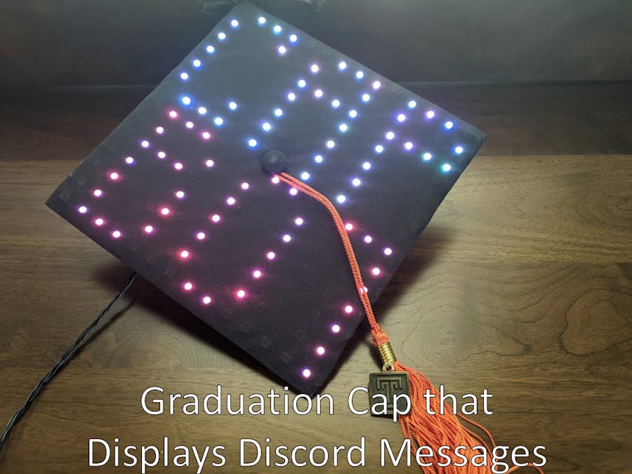
As a graduating Electrical Engineer, I wanted to do something special for my graduation. Having a party or doing something fun with my time is generally not my go-to idea so I decided to start a project instead. This would not be just any project; this was going to be a graduation cap with LEDs!
Now, that premise is kind of lame. Anyone can add LEDs to a graduation cap to show pretty colors or patterns. With this in mind, I decided the cap would need to be an LED matrix capable of displaying images and text. While this would have already made for a cool project, another layer needed to be added to the project. Something chaotic and spicy. So, like every other person on the internet, I turned to social media for ideas and, lo and behold, I had the perfect element of chaos to add!
It was then decided that people should be able to play messages on my graduation cap. The messages could be easily grabbed from some social media site and the cap would autonomously retrieve, format, and then display those messages in real time during the graduation ceremony. Finally, people are given the ability to say what they really feel during graduation and have it displayed on a tiny graduation cap for few people to see.
Requirements:The requirements imposed for this project were fairly simple. I wanted the cap to work completely on its own with no oversight from me. This means the cap had to retrieve and display messages without me checking social media or worrying about having content for the cap.
To make it easy to use, I wanted the system to work off a 5-Volt battery pack in my pants pocket. Using a 28500mAh battery pack to power the device, I wasn’t too concerned with power efficiency but I wanted to design the system to not waste power so the system can run a full 8 hours without a battery recharge.
Finally, I didn’t want to be spending too much on this as I am a poor college student with a fancy/expensive piece of paper and can’t afford nice things yet. This meant that I can’t be using fancy LED matrix solutions, instead opting to keep the whole project below $50.
Design:A graduation cap, for those who have never seen one, is a black square headpiece that measures 9.5in X 9.5in. The cap I bought for graduation uses a piece of cardboard to form the square base and a piece of black cloth is draped over, and secured to, the cardboard square. Another piece of cloth material is then affixed to the cardboard base, this time underneath the cap, so the cap can fit and stay on a head.
Generally, these bits of headwear are decorated with paint or something that can be affixed to the cap. In my case, I will need to strip the cap down to the base cardboard, add LEDs, then replace the black cloth on top and reassemble the cap. To make this whole process easier, addressable LED strips would be used to create an LED matrix and a microcontroller, underneath the center of the cap, would be attached to control the cap functionality.
Mechanical Design:After purchasing 16ft of WS2812B LED strip lights, I cut the strips into lengths with 14 LEDs per strip. This length was decided by trying to fit as many LEDs into a row as possible while leaving room on either side for wiring.
After 14 LED strips were cut, I marked the cap to indicate the center point of each LED strip on either side of the cap. This kept all the LED strips parallel to one another, providing a nice and even looking display.
Now began the job of soldering all the LED connections together. To make soldering easier, I attached the LED strips so the wiring zig zags from strip to strip, meaning I would have to reverse every other row in programming, but this reduced wire resistance and made soldering a breeze.
At this point, I tested the resulting matrix with the LED light controller that came with the product. After hooking everything up, I ran a basic routine that displays different colors on the LED string. This test ran successfully, lighting up every LED segment I fixed to the cardboard.
Now that everything was working, it was time to see what the cap would look like with the black cloth reattached. At this point, I was worried the LEDs wouldn’t shine through the black fabric very well. This fear proved to be unfounded after running the same test routine on the cap with the fabric in place. If anything, the LEDs were too bright and, drawing roughly 2.5 amps at full brightness, were starting to get hot I was worried it would start to melt something.
With all the mechanical components of the project working, I reattached the cloth cover using adhesive tape and hot glue, then began working on the control electronics.
Electrical Design:To control a WS2812B LED strip, a 5V data line is used to transmit data using a one-wire control interface. The LED strips need a 5V and GND connection using wire/circuitry that can handle a max of 3 amps (better to go over then under). The power for these strips comes directly from the 5V battery pack used to power the project.
An ESP32 was chosen as the main microcontroller for this project because I wanted a device that could easily connect to an internet network. Since ESP’s have built in Wi-Fi transceivers, it was an ideal chip to use for this project. ESPs use 3.3V power and output 3.3V logic levels so I needed to make sure the LEDs could work with 3.3V logic. The datasheet says that the logic HIGH threshold is 3.5V but, after testing, it was proven that these LEDs can work with the 3.3V logic. Ideally, a level shifter should have been used to convert 3.3V logic to 5V, but this is unnecessary since this is a DIY hobby project that does not need to be 100% reliable (even though I still try to meet that reliability metric).
This resulted in the circuitry seen below. An AMS1117-3.3V chip was used to create a clean (albeit inefficient) 3.3V power source and various pins were connected to male horizontal connectors.
To get everything into a small and thin package, I laid out the components to fit within a 1.5in x 2in circuit board. Thick traces and vias were used so I could easily manufacture the board on my CNC machine and attention was paid to make sure all traces could handle the required max current value.
The board then had to be assembled and soldered. Due to a mistake in the first board iteration, the pictured PCB will not match the finished PCB pictured above. The finished board, along with the cap, can be seen below:
All the parts used in this project are included in the following BOM. Overall, this project costs $30.70 without including a 5V battery source or the graduation cap.
Programming an ESP32 allows for multiple programming languages to be potentially used in this project. To simplify the handling of string data, Micropython was the chosen firmware language to do all my development in. While C and Lua would handle memory and program operation more efficiently, software efficiency is not the utmost priority. Instead, I wanted to make sure it was simple to connect to the internet and I wanted to log data onto the device without using an SD card interface. The Micropython request library allows for easy HTTPS connections and python has the benefit of dynamic memory allocation, allowing the HTTPS request to have a varying payload size without over-allocating RAM. Finally, the Micropython file system allows for files to be created and modified directly in flash memory, allowing for a simple text file to be created and written to whenever the cap displays a message.
The first challenge was to get the LED matrix lit up with custom images. To do this, I modified a WS2812B Micropython module I found on the internet and I added a “display_sprite()” function to generate a 196-index array that would be passed into the WS2812B module. This has the result of displaying an image from a 14x14 array filled with color values. Because I used a zig zag wiring pattern in the LED strips, I must reverse every other row to accurately display the image. Without this reversal, the sprites themselves would need to reverse every other row, which makes formatting/sprite creation more difficult, so the reversal is handled whenever the program generates the array for the WS2812B module. One of the sprites can be seen in the following image:
The second challenge was to create scrolling text across the LED matrix. I could not find any functionality within the WS2812B module or through a module on the internet to display text, so I had to create my own function. This involved creating my own 6x3 and 7x4 pixel font module (using pixel fonts I found online, I’m not that creative) along with a buffering protocol to shift the pixels one bit to the left, creating a scrolling text effect. The matrix was split into 7x14 pixel sections so the scrolling text could start on the lower half and continue scrolling into the top half before scrolling offscreen. To properly develop this functionality, I created 14 binary numbers in an array and used bit-shifting with some if-else logic to efficiently scroll text across the display. Function arguments allow for the text scrolling speed to be adjusted as well as an argument to allow the text to fully scroll of the screen.
The biggest challenge for the project was to connect the microcontroller to social media. Rather than allow anyone to post messages through a platform like Twitter or Facebook, I decided to use a Discord channel that most of the undergraduate Electrical Engineers within my university use to communicate with each other. This has the benefit of restricting people’s abilities to post messages, preventing random trolls from dropping f-bombs everywhere, while also allowing those who will be at commencement to participate.
To get this feature working, I had to create a Discord bot that could access the Discord API to get messages from the “General” channel of the Discord group. This bot was able to access the API through a special token, assigned to the bot, that acts to authorize the bot has the proper credentials. HTTPS GET requests are made to the Discord API, using the authorization token as a header field, and a JSON response of messages are sent back. The program then iterates through all the received messages looking for an integer code that corresponds to the bot’s Discord ID. If the ID is found within a message, indicating the bot was mentioned (“@GradCapBot”), the message is saved into a local variable and the program finishes examining all the messages.
Now that the program has a few messages to display, the program formats the text it will display and then calls “display_7x4_text()” with the new text as an argument. The program continues to display all the messages until all the messages have been displayed. This process runs in a loop so that the program is always looking for new messages to display. If there are no new messages to display, I didn’t want the cap to just sit idly without anything being displayed. For this reason, if there is no new message to display, the program displays one of the 10 images programmed into flash memory. Each image Is then displayed for 5 seconds and then the program checks for new messages again.
A rudimentary text filter was created to filter out 75 “bad words”, although this list is not very comprehensive. It is enough to filter out obvious curse words and slurs so there is piece of mind that I am not displaying something completely repugnant. While this filter may be easy to get around, I also included a function to save message details into flash memory so I can view the message text displayed along with who sent the message.
Operation:The program can be controlled through the REPL prompt when the ESP32 is connected to a serial monitor. Using the “Serial USB Terminal” Android app, my phone can act as a serial monitor that interfaces directly with the ESP32 to run some preprogrammed functions at the push of a button. This method also allows me to display non-formatted text or to display a particular sprite.
I made a one-minute video to explain how to send messages but it also shows how the project displays text to the screen. The video can be found here: https://www.youtube.com/watch?v=ThBNk4O7ULU


Comments