As part of Temple University's commitment to supporting frontline healthcare workers during the Covid-19 pandemic, a Temple University Covid-19 Task Force was designated to develop PPE and other necessary equipment to aid workers in Temple University Hospital. During the peak of the Covid-19 spread in Philadelphia at the beginning of April 2020, Temple University Hospital was expanding space to provide more beds for Covid-19 patients. This effort included designating a Temple sports facility, the Liacouras Center, as a surge facility to increase hospital bed availability in the Philadelphia area. This increase in hospital bedding meant that rooms were being created without necessary hospital infrastructure, including a lack of patient call systems to alert hospital personnel that a patient needs assistance. With this in mind, a low-cost hospital call system was designed for Temple University Hospital that was easy to use, quick to install and uncomplicated to manufacture in large quantities.
Requirements:The Temple Robotics team, a university organization aiding the Temple Covid-19 Task Force, was given the task of designing a patient call system for use in newly created surge rooms within Temple University Hospital facilities. The hospital requested that the call system activate an LED light when the patient call button is pressed, and that the light remain on until reset by a button on the “nurse” device. Hospital administration assumed the device would be active for 1 hour a day and requested that the device last for 1 month before the device batteries need to be changed. The final request was to design the device so they could be easily installed and removed once the surge capacity was no longer necessary. A requirement imposed by the Temple Robotics team was to design the system to be manufactured “in-house” meaning the circuit boards would be cut from single sided copper-clad with a CNC machine, and that the boards could be soldered using a reflow oven.
Design:Two devices were designed to fulfill the requirements outlined by hospital administration. These devices will be referred to as the “nurse” device, the device that goes outside a patient room with the LED indicator, and the “call” device, used by the patient to activate the LED on the nurse device. The nurse device and the call device use buttons to set, or clear, the LED on the nurse device. It was determined at the start of the project that the two devices would communicate through an RJ11 cable, as these cables are easy to acquire, come in many different lengths, and are inexpensive when compared to other signal transmission options.
Circuit Design:The nurse device was designed to act as the “base” device, so this device holds all of the logic circuitry to toggle the LED indicator. The battery pack is also part of the nurse device, so batteries can be easily changed by staff without patient interaction. The patient device was designed to be as simple as possible, consisting of a button to send a signal and an LED to indicate the button is actively pressed. The LED’s purpose on the patient device is to show the patient the device is registering input, providing peace of mind to a patient to know the system is responding to their input.
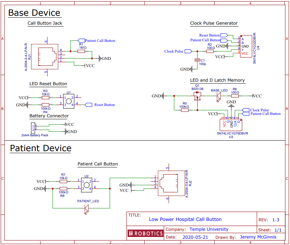
The electrical schematic above shows all of the electronics necessary to fulfill the given requirements. The patient device consists of a tactile button, an LED, an RJ11 jack and 2 resistors. When the button is not pressed, the signal pin of the RJ11 jack will always read as a logic 0. When the button is pressed, the LED turns on and the signal pin logic level changes to logic 1 until the button is no longer pressed.
The base device uses an OR gate and a D type latch to toggle the indicator LED state. The above image shows a logic diagram showing the necessary connections to toggle a D type latch from an “on” and an “off” button. The on and off buttons, normally a logic 0, will activate the OR gate when pressed. This activates the clock of the D latch, causing the logic level of the on button to be recorded to the latch. When the on button is pressed, the D latch input registers as a logic 1 and the D latch outputs a logic 1. When the off button is pressed, the D latch input registers as a logic 0 because the on button is still low. This has the effect of changing the output to a logic 0.
This logic was recreated in the circuit schematic, where the patient call button signal and the reset button are tied to the inputs of the OR gate. The signal output of the OR gate is connected in series with an RC network to the clock pin of the D latch, to extend the signal propagation time which ensures the logic level fed into the data pin of the D latch is stable. The output of the D latch is then connected to the gate of a MOSFET, which opens and closes to allow the indicator LED in the nurse’s board to turn on and off.
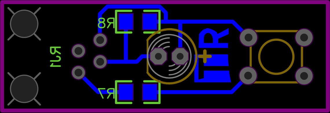
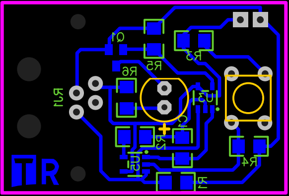
Nurse and Patient Circuit Boards:To keep to the requirement that these boards are to be manufactured with Temple University resources, a single sided circuit board was developed for the nurse and patient circuitry.
Care was given to spacing the traces and components so PCB end mills can be used to cut away large sections of copper. This board allows for all SMD parts to be placed and soldered before placing and soldering the 4 through hole components. Similar design attention was given to the patient board, seen below.
The following table are to scale pictures of the designed circuit boards which can be printed and transferred onto copper clad for chemical etching. Gerber files for the circuit boards can be found in the files area of this project.
The following components were used to create the circuits in the earlier circuit diagram. A lithium ion battery was used to provide power to the devices, so a Molex connector of the female type was used so the battery could be easily removed and swapped for a fresh one.
Assembly starts by producing the etched circuit boards, whether by CNC routing or chemical etching, from the provided gerber files or etching board layout images. Creating the PCBs can take anywhere from 20 minutes to 2 hours depending on the process you use. Component assembly should take about 30 minutes, if done in batches of multiple boards than it can take as little as 15 minutes to assemble both boards.
To assemble the patient board, begin by laying out all the parts necessary for the patient board.
Then, place solder paste on the two 1206 resistor pads. Using a reflow gun or hotplate, solder the resistors to the board.
Next, solder the LED, microswitch and RJ11 connector to the patient board.
To assemble the nurse board, lay out all of the components necessary for the nurse board.
Now, if you have a solder paste stencil, affix solder paste to the nurse board wherever an SMD part will go.
Place all of the SMD components according to the circuit schematic and component labels seen in the nurse board layout image. The board should now look like this.
Finish soldering the nurse board by attaching the LED, microswitch, battery connector and RJ11 connector.
Now, the board assembly is completed.
After building the circuitry and observing circuit operation, the device will consume 80 mA a day assuming the circuit is active for one hour a day and off for the rest.
Device Cases:A case was designed for both the patient and the nurse boards. Button tabs were directly integrated into the case, making for an uncomplicated assembly process. Because these devices were to be used in temporary locations, notches are located on the underside of the nurse case, where magnets can be fitted, so the case can be affixed to a metal doorframe. No fasteners are necessary to assemble the patient case and the necessary hardware for the nurse case is listed below:
To assemble the patient case, place the patient board into the patient case base plate. The profile of the board should rest between the two raised walls on the surface of the plate.
Place the patient case top over the patient board so that the bottom plate and top piece lock into one another. Now the patient device is full assembled.
To assemble the nurse case, place the ¼” screw into the mounting holes of the nurse board. Attach a nut to the base of the screws and tighten until the board is fixed in place.
Now, place the walls over the bottom case plate and attach the battery to be used. In this example, a standard 2xAA battery pack was used to provide power to the board. The top pin of the battery port is GND so ensure the battery polarity matches this.
Attach the top plate and insert the 1” screws into the corner holes. Tighten nuts onto the 4 corner screws and the case is assembled.
To operate these devices, connect an RJ11 cable (4P4C cable type) to the patient device and the nurse device. Press the button on the patient device, and the nurse device LED will turn on. Press the button on the nurse device, and the LED will turn off.
This project was made for Temple University Hospital by members of the Temple Robotics Club.


Comments
Please log in or sign up to comment.