


Hardware components | ||||||
 |
| × | 1 | |||
Software apps and online services | ||||||
 |
| |||||
Hand tools and fabrication machines | ||||||
 |
| |||||
| ||||||
Hi there!
Version 2 of Hardware is Up! Check GitHub! Article coming here soon enough!
Story of Version 1 is down below!
If you want to stay up to date, progress will be published in GitHub!
After developing a small part of the code and reading more thoroughly about the micro-controller, plus wanting to address some short comings. I am developing V.2 of the project! The fundraising campaign is also closed! I can support the project on my own now! Thank you all that you contributed! I will try my best in the long term to finally deliver! For any delay that happened I can only say one thing... Real life happened.. Work, work, work, studies and a pandemic on top of it! it can happen to everybody! But I will continue and will finally deliver! Thank you! For everything! Anyhow finally I am starting to have a little bit more time to do this!
The new design is based on 3 boards!
- The magnetic encoder board, cause precision!
- The CPU board, again based on the same micro but that can change!
- And the power board! With higher input voltages up to 30V and could deliver up to 10A, although probably not sustained and really limited by the connectors at this point.
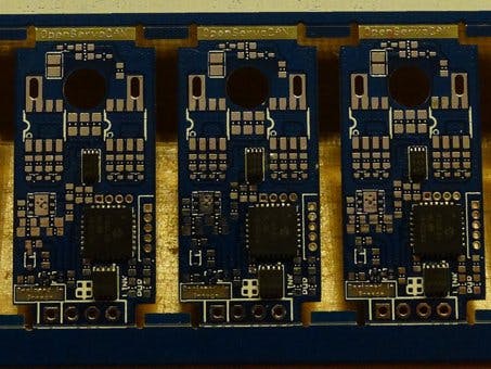
And the demo boards from OSHPARK are already here and look fabulous!
Main Story of the Project - Version 1 Hardware
One of the major problems, especially back on the day was servos. Most people, including me, would use standard size hobby RC servos for all their robots. These "servos" were expensive and dumb, and although Chinese manufacturers have nowadays solved the price problem, few and still very expensive are the solutions that offer a "true servo," a motion controller with proper feedback! And that's exactly where this projects stems from.
And thus OpenServoCAN is born! An alternative to the boring control boards inside standard size hobby servos!
It was a very long time I wanted to make a project like this! Most, for the more expensive ones, hobby servos offer no feed back. You send them a signal and hope they will reach the targeted position. This might be good enough for uses in the RC world, but not good enough at all for those building robots or anything of a kind that needs feedback.
Although I am aware that another OpenServo Project exists, I wanted to put my own touch into the matter and I tried to do quite a few things better, at least compared to the first version (I have not reviewed the second).
- Added CAN-Bus! Yes, that´s a good thing! It might complicate some things especially for beginners but that´s on what most "unobtainium" servos work in the market. I have not yet decided the communications protocol, but I am leaning towards CANopen, suggestions are open!
- Can support either a potentiometer or an encoder (quadrature or not) for positional control
- Can operate from 5V - 15V safe zone, but most probably will not have a problem with a 4S LiPo. Current limiting will be done by software so, if you want to break the DC motor inside or not is totally up to you!
- Beefed up MOSFETs with individual MOSFET drivers, just to be able to push that switching frequency to the right spot without worrying too much!
During some very nice Christmas Holidays, I spent the nights designing, what will become one of my smallest, but most powerful projects. After around two weeks, I came out with this!
And... this!
And although you can download the zip and find all the components needed in the eagle files, for your convenience, I am including here a photo of the BOM.
Now of course, I am no stranger to producing my own PCBs, but the level of precision and miniaturization this project required, was well out of my league, so without further a do, I exporter my Gerber files and contacted JLCPCB! And after another week of waiting this what came knocking at my door!
Well... that´s not one,
that´s not two but that´s 100 PCBs! You see, I took my sweet time at panelizing the PCBs, so in a single 100mm x 100mm PCB I could fit 10 of my O.S.CAN boards!And of course the second and most important step was to start soldering the darn things!
Now you might think, that for something so small, you might need very expensive tools. But you´d be dead wrong. Any hot air station, which you know how it works, should do the trick! After all, my tools do not cost more than 100€ together, depending on where you buy!
And so I started doing the rest of the boards, the "problem" if you would call it one, is that for development phase I need more than one board. I need not only test the hardware but also the communications base on the CAN-Bus. So I continued...
But as you can see, there are things missing! A lot of them to be exact and that´s exactly also where I need your help! Also know that this article is far from finished, if you want to see daily updates follow me at Instagram. Videos will be coming about its operation at YouTube. Code and schematics will be updated at GitHub and EEVBlog!
And not to worry, I got many servos waiting for the modification (and a mess to clean )!
Update #1 01/05/19
Due to me having a day-job, the date of completion of the project is postponed.
Still having some extra money now I can afford some extras. In fact the first order of parts from Mouser are here and there are enough to populate 10 PCBs!
The first three are already made and are being tested!


Comments
Please log in or sign up to comment.