I have been following hackster.io for many years now. All those projects helped me learn a lot of stuff. It was always my dream to create a project in hackster. The contest Touch Less Do More looked like the best way to start my hackster journey. When I decided to participate I didn't have the required Arduino MKR WiFi 1010 development board. So, I decided to apply for hardware with my idea Clip-ON Move-ON and I eventually won an Arduino MKR WiFi 1010 which enabled my participation. I would like to thank Hackster, Arduino for hosting such an amazing event in the difficult of times; creating a positive vibe among the creators and enabling us to provide our ideas in the fight against Covid-19.
THE IDEAThe core idea of Clip-ON is to remind, help, and alert people to maintain social distancing in public places. Since the backpack has become such an inevitable part of our lives, the concept is to attach the Clip-ON to the backpack and let it do the job; while we move across the day with less fear and a sense of happiness of playing a positive role in the fight against Covid-19. This device not only helps the wearer but also the people nearby by reminding everyone to maintain social distancing.
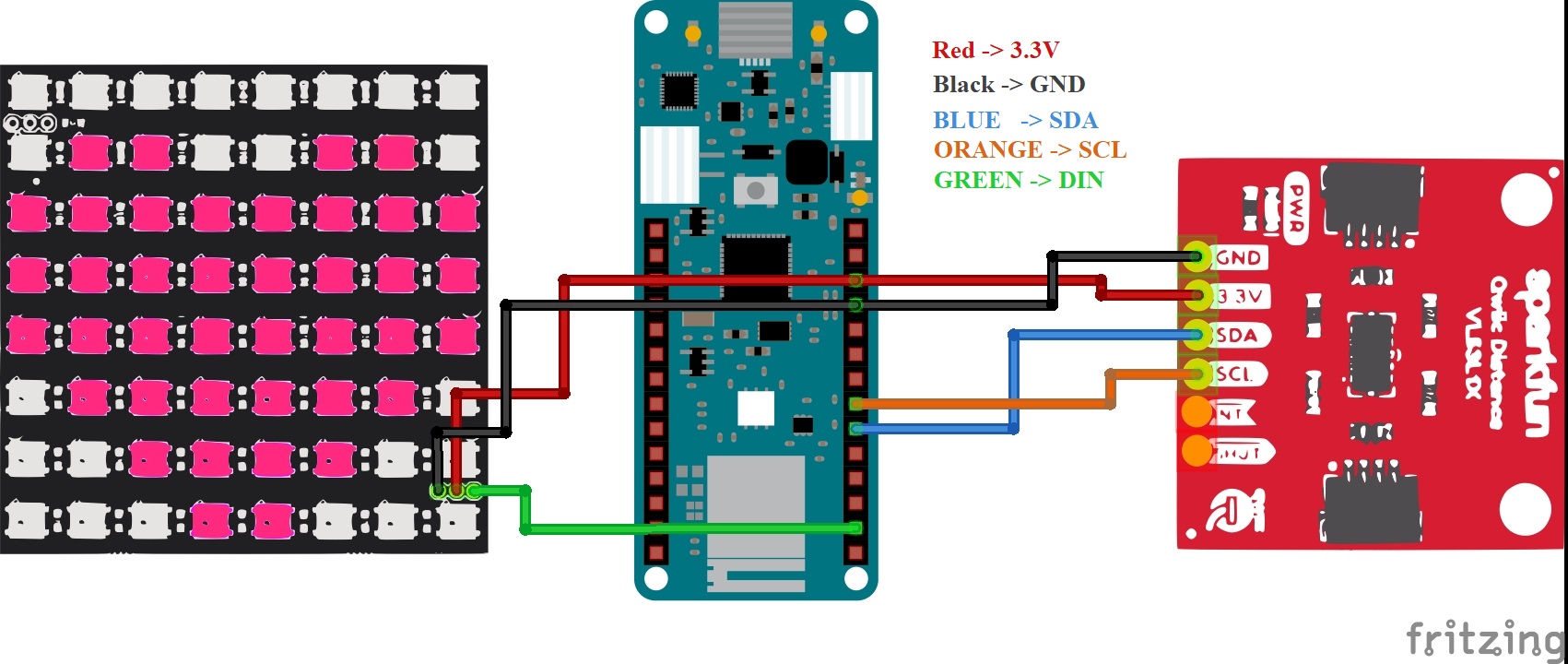
TECHNICAL DETAILSThe Clip-ON makes use of an 8x8 Neopixel Matrix, a VL53L1X Time of Flight (ToF) sensor, an Arduino MKR Wifi 1010 development board, and the smartphone of the user. The ToF sensor and LED Matrix are attached to the back of the backpack. They are connected to the MKR board which is inside the bag through some wires. The setup is powered by a 3.7V Li-Po battery which is also inside the bag. The ToF sensor continuously monitors if anyone is present within a distance of 1.5 meters; if someone is present the LED Matrix will start to flash a sequence of images alerting the person and enables social distancing. Once the person moves backward and reaches a safe distance of 1.5m, the LED Matrix turns OFF.
An android app that is provided with the device, lets the user control the device via the Bluetooth Low Energy Module present in the MKR board. The user can turn the device ON, turn it OFF, change brightness, and can even display custom scrolling texts like "Wear Mask" or "Stay at a Distance" or anything of their choice. The circuit schematic, the associated Arduino code, and the development of the android app are provided below in detail for the reader.
ARDUINO CODEThe Arduino library dependencies that are required for the project are listed below,
- Scheduler (This manages the various loops that are run simultaneously.. This is such a lifesaver!)
- ArduinoBLE (The Bluetooth Low Energy library for Arduino. It's so elegant!)
- Adafruit_GFX, Adafruit_NeoMatrix, Adafruit_NeoPixel (These makes driving the LED Matrix a piece of cake!)
- Wire.h (The I2C Library to communicate with ToF sensor. This does all the painful stuff for us :) )
- SparkFun_VL53L1X.h ( ToF sensor library. It's the reason I didn't open the sensor datasheet)
I want to thank the creators of these libraries, without which this project would have taken a lifetime for me to complete this project... LOL!
The code is divided into parts for easier understanding and implementation. The parts are,
This is the main Arduino file. It combines all the parts of the project. The following code includes all the necessary dependent files.
#include <Scheduler.h> //Include Scheduler Library
#include "BLE_Handler.h" //Include BLE_Handler
#include "Led_Handler.h" //Include Led_Handler
#include "Lidar_Handler.h" //Include Lidar_Handler
#include "Sprint.h"
The void setup() function initializes all the components of the project ( LED Matrix, BLE, ToF sensor ). Then Serial communication is initialized. Then the three loops ( BLE_Routine, LED_Routine, LIDAR_Routine ) are started using the Scheduler, which in real-time will manage the tasks of the three infinite loops ( Similar to an RTOS ).
void setup() {
  // put your setup code here, to run once:

  BLE_Initialize(); //Initialize BLE
  LED_Initialize(); //Initialize LED
  LIDAR_Initialize(); //Initialize LIDAR

  Serial.begin(115200); //Begin Serial Communication

  Scheduler.startLoop(BLE_Routine); //starts BLE_Routine Loop
  Scheduler.startLoop(LED_Routine); //starts LED_Routine Loop
  Scheduler.startLoop(LIDAR_Routine); //starts LIDAR_Routine Loop
}
In void loop() function, no task is present this is because all the tasks are taken cared for by the three loops initialized previously. This loop() is present because of the Arduino template. Else the code won't run. The yield() function is a function of the Scheduler library, the function must be called periodically to ensure the proper functioning of all the loops.
void loop() {
   yield(); //Scheduler function- this ensures all the loops are run.
}The BLE_Handler handles all the tasks related to BLE. There are two main functions in BLE_Handler. They are BLE_Initialize(), and BLE_Routine().
The BLE_Initialize() function sets the name to the BLE device, creates the BLE service, and adds the characteristics to the BLE service. Then advertises the device for other devices to connect with it. For further details on the functions used, you can refer to the source files of the libraries.
void BLE_Initialize(){

  pinMode(ledPin, OUTPUT);

  if (!BLE.begin())
    Sprintln("starting BLE failed!");

  BLE.setLocalName("CLIP-ON MOVE-ON");
  BLE.setAdvertisedService(ledService);

  ledService.addCharacteristic(switchCharacteristic);
  ledService.addCharacteristic(brightnessCharacteristic);
  ledService.addCharacteristic(scrollingCharacteristic);
  ledService.addCharacteristic(textCharacteristic);
  BLE.addService(ledService);

  switchCharacteristic.writeValue(0);
  brightnessCharacteristic.writeValue(0);
  scrollingCharacteristic.writeValue(0);
  BLE.advertise();

  Sprintln("Clip-ON Move-ON Availabe to Connect");
  }
The BLE_Routine() function waits for any device to connect; once connected it starts to listen to the characteristics. Once any value is changed by the user from the app, the corresponding value in the code is updated. The values that can be changed are power (power on/off the device), brightness (brightness of LED), scrolling text.
void BLE_Routine(){

  BLEDevice central = BLE.central();
   yield();
  if (central) {
  Sprint("Connected to Device: ");
  Sprintln(central.address());

  while (central.connected()) {
    if (switchCharacteristic.written()) {
      if (switchCharacteristic.value()) {   // any value other than 0
        Sprintln("POWER ON");
        power = true;
        turnOnText =  true;
        digitalWrite(ledPin, HIGH);         // will turn the LED on
      } else {                              // a 0 value
        Sprintln(F("POWER OFF"));
        power = false;
        turnOffText =  true;
        digitalWrite(ledPin, LOW);          // will turn the LED off
      }
    }

    if (brightnessCharacteristic.written()) {
      brightness = brightnessCharacteristic.value();
      Sprintln(brightness);
    }

    if (scrollingCharacteristic.written()) {
      scrolling = scrollingCharacteristic.value();
      Sprintln(scrolling);
    }

    if (textCharacteristic.written()) {
      scrollingText = textCharacteristic.value();
      Sprintln(scrollingText);
    }
    yield();
  }


  Sprint(F("Disconnected from central: "));
  Sprintln(central.address());
  yield();
}
}The LIDAR_Handler handles all the tasks related to the ToF sensor. There are two main functions in LIDAR_Handler. They are LIDAR_Initialize(), and LIDAR_Routine().
The LIDAR_Initialize() function iniltializes the ToF sensor.
void LIDAR_Initialize(){

  Wire.begin();

  if (distanceSensor.begin() != 0) //Begin returns 0 on a good init
  {
    Sprintln("TOF Sensor failed to begin. Please check wiring. Freezing...");

  }
  ("TOF Sensor online!");
  }
The LIDAR_Routine() keeps on ranging and measures the distance. If the measurement is less than 1.5m, then it alerts the LED_Routine() to display the alerts to the person.
void LIDAR_Routine(){
  yield();
  if(power){
  prev_distance = distance;
  distanceSensor.startRanging(); //Write configuration block of 135 bytes to setup a measurement
  while (!distanceSensor.checkForDataReady())
  {
    delay(1);
  }
  distance = distanceSensor.getDistance(); //Get the result of the measurement
  distanceSensor.clearInterrupt();
  distanceSensor.stopRanging();

  if(signalStatus()){
  int slope = distance - prev_distance;
  }
  else{
    Sprint("Signal Fail");
    }

  if(distance < 1500) {
    led_sequence = 1;
    }

  if(distance > 1500) {
    led_sequence = 0;
    }
  yield();
    }
}The LED_Handler handles all the tasks related to the ToF sensor. There are two main functions in LED_Handler. They are LED_Initialize() and LED_Routine().
The LED_Initialize() function starts the LED matrix, sets the brightness and displays nothing ( that's good!).
void LED_Initialize(){
  matrix->begin();
  matrix->setTextWrap(false);
  matrix->setBrightness(brightness);
  matrix->setTextColor(colors[0]);
  matrix->fillScreen(LED_BLACK);
  matrix->show();
  }
The LED_Routine() does a couple of things; they are
- Display an emoji (happy) during power-up.
- Display an emoji (sad) during power-down.
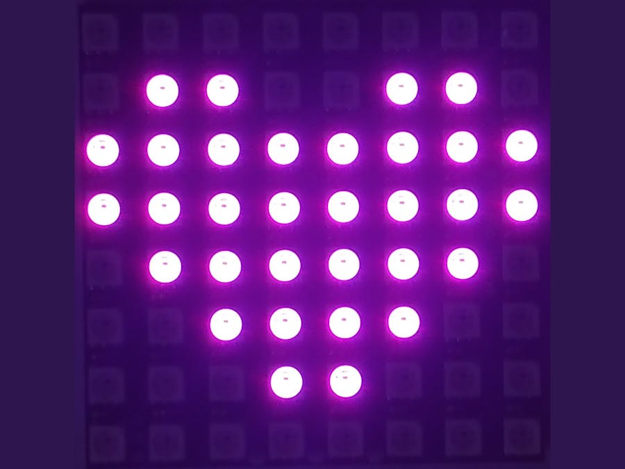
- When someone is within 1.5 meters, the symbol 'X' flashes twice, then the arrow ↓ will start to scroll asking the individual to move back. Once he/she has moved to a safer distance, the LED will flash a heart ♥.
- If the ClipOn user wants to display scrolling text, he/she can enable it in the app and then type in the text that is to be displayed. Once that is done, the desired text will keep on be scrolling. ( For eg: "Wear Mask" this can remind all the nearby people to wear masks!! )
void LED_Routine(){
  yield();
   if(turnOffText){
    Sprintln("SHUTDOWN SMILEY");
    display_bitmap(14, LED_GREEN_HIGH);
    delay(2000);
    matrix->fillScreen(LED_BLACK);
    matrix->show();
    turnOffText = false;
    }

  if(power){
   if(!scrolling){
      if(ledOn){
        ledOn = false;
        matrix->fillScreen(LED_BLACK);
        matrix->show();
        }
    }
   if(scrolling){
      char *s2 = new char[scrollingText.length()+1];
      strcpy(s2, scrollingText.c_str());
      ledOn = true;
      display_scrollText(s2);
      yield();
   }
  if(turnOnText){
    Sprintln("STARTUP SMILEY");
    display_bitmap(12, LED_BLUE_HIGH);
    delay(2000);
    matrix->fillScreen(LED_BLACK);
    matrix->show();
    turnOnText = false;
    }

  if(led_sequence == 1){
  matrix->setBrightness(brightness);
  Serial.println(led_sequence);

  for(int i=0;i<cross;i++){
    Sprintln("Displaying Red Cross");
    ledOn = true;
    display_bitmap(8,LED_RED_HIGH);
    delay(200);
    matrix->fillScreen(LED_BLACK);
    matrix->show();
    delay(200);
    }

  while(distance < 1500){
    Sprintln("Displaying Green Arrow");
    for (uint8_t i=0; i<8; i++){
      display_bitmap(i, LED_GREEN_HIGH);
      delay(100);
            }
  ledOn = true;
    }
  Sprintln("Displaying Heart");
  display_bitmap(9, LED_PURPLE_HIGH);
  delay(1000);
  led_sequence = 0;
  matrix->fillScreen(LED_BLACK);
  matrix->show();
    }

  if(led_sequence == 0 ){
    if(ledOn == true){
    matrix->fillScreen(LED_BLACK);
    matrix->show();
    ledOn = false;
    yield();
            }
        }
    }
}This is a header that enables or disables the debugging feature. if enabled, the Arduino will print the debugging values via Serial. Else it won't be printed.
#define ENABLE_PRINT

#ifdef ENABLE_PRINT
#define Sprintln(a) (Serial.println(a))
#define Sprint(a) (Serial.print(a))
#endif

#ifndef ENABLE_PRINT
#define Sprintln(a)
#define Sprint(a)
#endif
Only the crux of the entire code is explained if the reader has any difficulties in using the source code he/she can always find the solution online (Just Google it!!). Also reading the source code of the library helps!!.
MIT APP INVENTOR
MIT App Inventor is an amazing tool for the easy development of a proof of concept app. With no prior experience in Android app development, it was still a cakewalk for me to use MIT App inventor. It's just so intuitive a simple. The MIT App Inventor BlutoothLE is an amazing extension! without which the app is not possible. The app UI design and the design of the blocks are given below for anyone interested in learning.
The basic working video is attached. The Clip-ON is powered up. The text "Covid" is made to scroll. The distance goes below 1.5 meters, the LEDs alert the user and asks the person to move back. Once he/she moves back and reaches a safe distance, the LED flashes a heart and starts to display the scrolling text.
FAILSIn the initial idea, I proposed to use Tensorflow Lite and train an ML classifier and classify the ToF sensor data and alert the user accordingly. I was able to train a good model and deploy it to the sensor (after many struggles and reading the TF Lite library extensively as no official support is present currently for the Arduino MKR Wifi 1010 board). The deployed model predicted good results but the process was too slow for the results to be useful. As the ML-based approach was actually an overkill, I decided to leave it behind and develop the project. But I surely will post a project with TF Lite on this board (Follow me for that!! and ideas are also welcome). Also in my initial idea, a ToF sensor was on the front side of the backpack also with a few LEDs which blink and alert the user when he/she's too close to someone. But the VL53L0X sensor which I intended to use in the front, seems to not work properly when operated together with VL53L1X (Even after setting different I2C addresses for the 2 sensors. They boot successfully and also give out values but the values from VL53L0X are not proper.).
Okay, that's it for now!!. Stay Home Stay Safe


_3u05Tpwasz.png?auto=compress%2Cformat&w=40&h=40&fit=fillmax&bg=fff&dpr=2)
Comments
Please log in or sign up to comment.