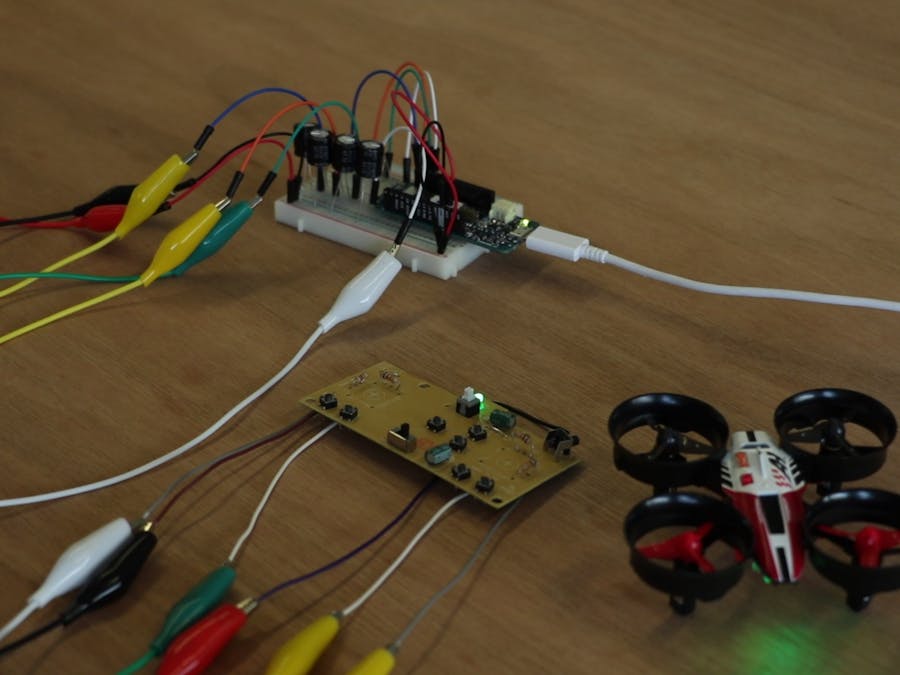
I find drones fascinating, those little flying machines that can do about anything. When I got the opportunity to do a project with cool technology I decided to make a boy's dream come true, controlling a drone with your mind.
In the research, I did for this project I didn't find any tutorials that covers how you can hack a drone controller easily. Most of the tutorials available are about how you can create your own drone using an Arduino or how to hack the transmission protocol.
This tutorial covers the most basic concept of hacking a PCB to control it digitally. The aim of this tutorial is to learn you the basic concepts that will enable you to experiment on your own with a drone and create something fun.
NoticesYou potentially can kill your drone or the controller and make it unusable.
This project will not cover how to steer your drone only lift-off and landing.
You don't necessarily need a MindWave / EEG sensor, you can use any input you want. But controlling a drone with your mind is pure awesomeness!
Video tutorialSkills you needThis tutorial assumes you have some kind of experience with soldering and desoldering.
Parts list- Drone + controller
- Soldering Station + accessories (braided copper wire, desolder pump, helping hand, solid core wires, tin)
- Multimeter
- MindWave sensor
- Arduino MKR1000
- Breadboard
- 4x 100uF capacitors
- 4x 220Ω Resistors
- 12x Jumper wires
- 6 Crocodile clip wires (optional)
You also need 4 resistors with an not yet know resistance value.
Phase 1: Drone PCBYou can use almost any drone you want. Most of the controllers work with two-axis joysticks. Those joysticks we are going to bypass.
First, open the case of your controller. This controller uses two 1.5v batteries which are approximate 3.3v. This value is the same as the output of the Arduino MKR1000.
It is possible to use another Arduino of your liking, but be aware you can break the circuit board if you give it more voltage that the PCB can handle. ( I speak from experience. )
Mesure with a multi-meter what the middle, high and low voltages are of the joysticks once powered. Write them down for later use.
Desolder the joystick components from the PCB.
In reality these joystick components are just potentiometers. A potentiometer is an analogue variable resistor. You can mesure the maximum resistance with an multimeter. Connect the multimeter to the + and - to read the resistance.
Solder (in this case 10Ω resistors) 4 resistors on the holes of the + and - of the joysticks to complete the circuit.
Also, solder solid core wires to the + (B+ on this board) and - (B- on this board) ports on the PCB. And solder solid core wires to the signal ports of the joysticks.
Now you have prepared your controller for the next step.
When you use AnalogWrite on with your Arduino the output will be a PWM (Pulse Width Modulation) signal. The win will turn its own value HIGH and LOW in a determined frequency.
Our prepared PCB does not like PWM, it is expecting a steady voltage.
To create an analogue value we can use a variety of digital to analogue converters like a DAC chip or an RF Ladder filter.
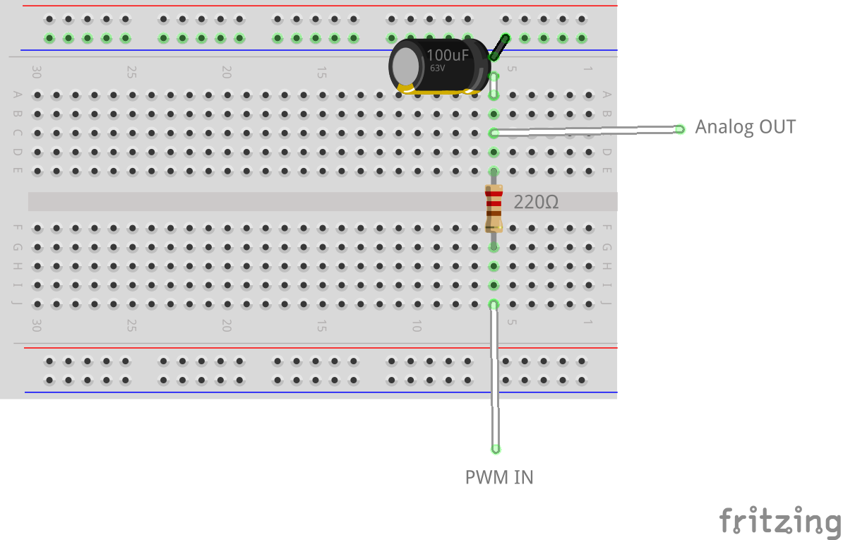
Because of that I want to keep this project so simple as possible I will learn you how to use a Low Pass Filter, that will give us the desired output.
To create a Low pass filter you need a capacitor and a resistor.
One of the characteristics of a low pass filter is that the analogue voltage will gradually change (it takes some time). This circuit works best for me because it gives me the desired outcome and uses a low amount of parts.
The main part of our circuit is the low pass filter we created recently. Make four of them in a row and we have an analogue voltage for all four of the controller inputs.
Connect the right outputs to the correct inputs on the controller PCB. Make sure you got it correctly before uploading the Arduino Sketch.
The standard drone layout is as followed:
- Throttle => up / down on the left side of the controller
- Yaw => left / right on the left side of the controller
- Pitch => up / down on the right side of the controller
- Roll => left / right on the right side of the controller
Once everything is connected you can upload your sketch to your Arduino MKR1000. You can find the sketch at the bottom of this tutorial.
The Arduino will replace the batteries and can send signals (as voltages) to the bypassed joysticks. At this moment you can build your own programs en experiments to control the drone with PWM.
I will now show you how to use Processing and a MindWave sensor to lift-off the drone.
Phase 4: Mind controlInstall all the drivers on your computer. This MindWave sensor comes with a CD.
Pair the MindWave sensor to your computer with Bluetooth. Hold on button up for 3 seconds and the blue led will blink twice, it is now discoverable.
Once connected you start processing.
Install the MindSet library created by Jorge C. S Cardoso for processing from http://jorgecardoso.eu/processing/MindSetProcessing/#download
Unzip the library in your libraries folder. You can find the libraries folder in your processing folder.
Make sure your com-ports are correct in the setup, or you will end up with an error. You can find the com-ports in your device manager.
You can also find the com-port of the Arduino under "Tools" in the Arduino IDE at "Port"
You can also find the com-port of the MindWave sensor in the ThinkGear Connector Preferences (you get this program when you instal the drivers) under "Options"
receiver = new Serial(this, "COM10", 115200);
mindSet = new MindSet(this, "COM5");
Processing communicates with your Arduino via Serial. You can alter the Processing code to your liking, read the comments in the sketch to understand what is going on.
Run your Processing sketch and concentrate on your drone. When your concentration level goes above 40% the drone will lift off. How harder you concentrate the more aggressive the drone will be. You can land the drone by letting your mind wander off and stop concentrating.
I hope this tutorial gave you some insight on how simple it can be to hack a drone controller (or any PCB) and give it another input. You can figure out with experimentation how to get other inputs to control and how to make other movements in addition to lift-off and land.
I am excited to see what cool stuff you guys will make!


Comments
Please log in or sign up to comment.