


Hardware components | ||||||
_ztBMuBhMHo.jpg?auto=compress%2Cformat&w=48&h=48&fit=fill&bg=ffffff) |
| × | 1 | |||
| × | 1 | ||||
| × | 1 | ||||
 |
| × | 3 | |||
 |
| × | 1 | |||
 |
| × | 1 | |||
 |
| × | 1 | |||
This project provides a simple way of switching between two power sources. Using a light sensor (BH1750) and Arduino relay module, select one of two available power sources. For example, use solar panel power during daytime and switch to regular electrical source when light is not sufficient.
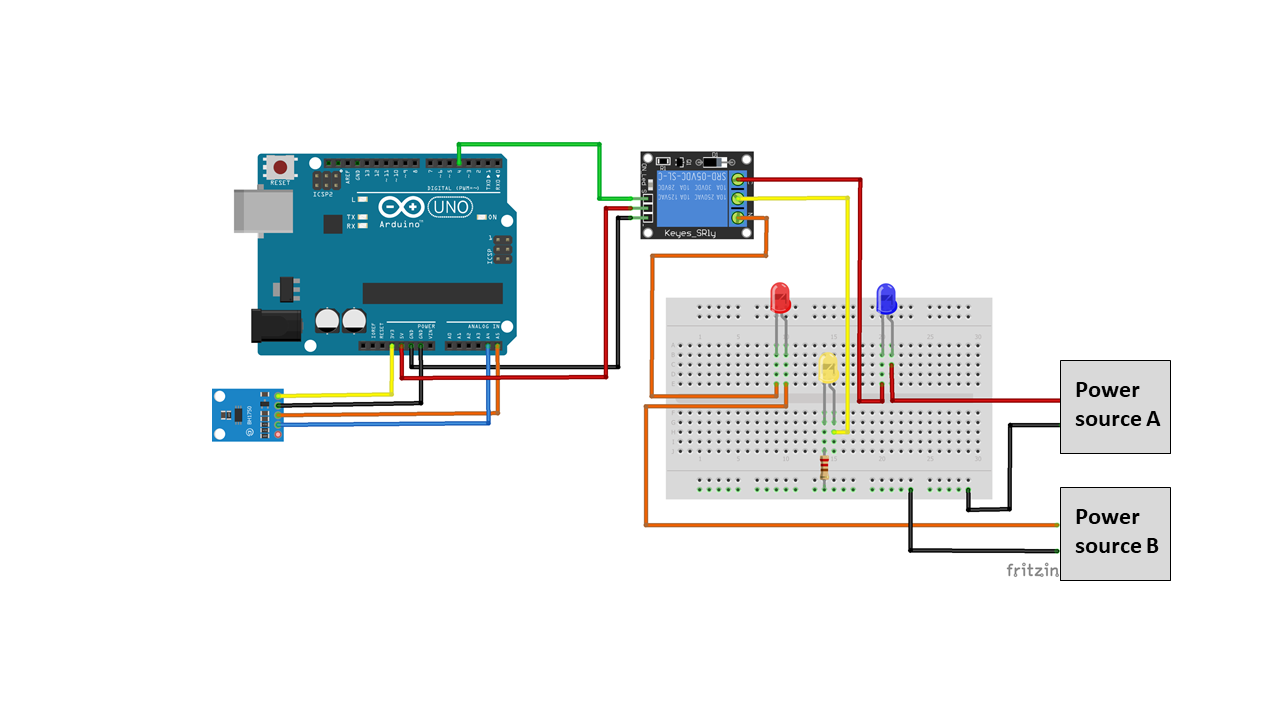
Setup for on-bench demoArduino 5V relay module has 6 connection points. One end provides pins to operate the relay module and the other end provides connection to power sources. DC+ and DC- provide power necessary to operate the relay module. In this project, 5V relay module is used. So, DC+ pin is connected to Arduino’s 5V, and DC- pin is connected to Arduino’s Gnd. IN pin is where logic signal (control signal) input is entered. When IN pin is logic low (0V), COM and NC (normally closed) are connected. When IN pin logic is high (5V), COM and NO (normally open) are connected. The relay module works in the opposite way if jumper block connects L and middle.
For example, when the surround is dark, use electrical power(NC connection), and connects to solar power (NO connection) when the surround is bright.
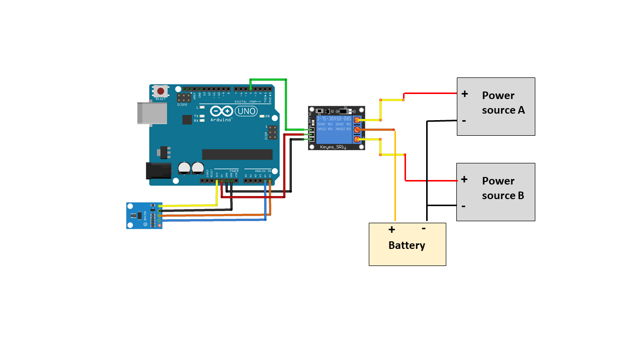
Relay module connection
DC+ -- Arduino 5V
DC- -- Arduino Gnd
IN -- Arduino Digital pin 4
NC -- power source A (electrical power)positive terminal
NO -- power source B (solar power)positive terminal
Com -- positive terminal of output device
And power source A’ Gnd, power source B’s Gnd, and the output device’s Gnd are all tied together.
When IN pin is low, current flows from power source A -> NC -> Com -> Device + -> Gnd. When IN pin is high, current flows from power source B -> NO -> Com -> Device + -> Gnd.
In this demo, to help visualize switching actions, a blue LED is connected to power source A, a red LED is connected to power source B, and a yellow LED is connected to the output device. The yellow LED is supposed to be ON always. When power source A is ON, the blue LED is turned on. And when power source B is connected, the red LED is turned on.
BH1750 light sensor is a popular sensor used in mechatronics to sense light intensity. It has 5 pins and uses I2C communication. Its operation voltage is 3-5V. “ADDR” is used to use the alternate address for this device. If not connected, the default address is used in I2C communication. Connection to Arduino is like the following:
VCC -- Arduino 3.3V (or 5V)
GND -- Arduino Gnd
SCL -- Arduino A5
SDA -- Arduino A4
ApplicationThis idea can be used to select power source between solar and electrical sources depending on how bright the surrounding is. In this application, there are two power sources, a regular AC adapter and a solar power from solar panel. A power station (Jackery Explore 240) is charged by either AC source or solar panel depending on the measured light intensity. And an NUC8 mini PC draws power (40W) from the power station and runs 24x7. Connection is the same as on-bench demo except LEDs are not present. AC adapter power source is connected to NC terminal of relay module, and solar panel power line is connected to NO terminal. When the value read from BH1750 is over the threshold, raise the relay IN HIGH to connect to solar panel power. Otherwise, puts the relay IN LOW to connect to the AC source.
The following picture shows the power station is charged by two sources depending on how bring the surrounding is.


Comments
Please log in or sign up to comment.