


Hardware components | ||||||
 |
| × | 1 | |||
 |
| × | 1 | |||
 |
| × | 1 | |||
 |
| × | 1 | |||
 |
| × | 1 | |||
 |
| × | 1 | |||
| × | 1 | ||||
| × | 1 | ||||
| × | 1 | ||||
| × | 1 | ||||
| × | 1 | ||||
Software apps and online services | ||||||
 |
| |||||
| ||||||
This Hand presents a new fast implementation of an assistive prosthetic upper limb that can be developed according to special demands of rehabilitation.
Introduction:
Initially, the bio-signals were obtained from the muscles and converted into electrical signals through electrodes so that we could utilize them to issue control commands. However, before that, it was necessary to process these signals through amplification and filtering stages. After obtaining the appropriate signal, it was fed into a microcontroller, where programming code was written to control the motor connected to the fingers of the hand to perform the desired movement and send control commands according to the contraction and relaxation of the muscles.
Bio Section:
In the case of voluntary contraction of skeletal muscle, the range of electrical muscle potentials varies between 50 microvolts to 5 millivolts, with a duration ranging from 2 to 15 milliseconds. These values (amplitude and time duration) change depending on the anatomical location of the muscle, its size, the position and type of electrodes, and the degree of muscle contraction. In the case of a relaxed muscle, there will be no effective potentials.
The captured signal is characterized by its irregular stochastic nature, which is evident from the wide range of its value:
mV ∼ Amplitude = 50 μ V
or its frequency bandwidth:
Frequency Bandwidth = 20 Hz
This is attributed to the variation in the number of muscle fibers and motor units activated from one muscle to another, especially with the differences in shapes and sizes of the muscles that make up the human body. The electrodes capture the potentials resulting from contraction, which are then amplified and filtered.
- Determinants of EMG Signal Amplitude:
Can be broadly classified into biological and technical factors:
• Biological determinants include:
- Muscle contraction strength (related to the number of activated motor units).
- Muscle size.
- Muscle location.
- Thickness of subcutaneous fat (electrical insulator).
• Technical determinants include:
- Skin preparation (determines skin impedance).
- Distance between electrodes.
- Electrode placement relative to the muscle.
- Orientation of electrodes (in relation to muscle fiber direction).
Electrodes:
Muscle electrical activity can be observed and recorded using electrodes, which represent the essential component in applications for acquiring and converting bio-signals into electrical signals. The process of capturing bio-signals involves the transfer of ionic current through the body into an electrical current via the electrode and then into input circuit elements. This process relies on oxidation and reduction reactions that occur when electrodes interact with the viscous ionic solution.
Regarding the amplifier, due to its high input impedance, the current flowing within the amplifier can be neglected when DC biasing is applied. The passage of current through the electrode results in the removal of ions from the surface and oxidation of surface atoms, which become positively charged ions in the solution. In general, when we have two ionic solutions with different activities separated by a semi-permeable membrane with ionic selectivity, an ionic potential is generated between the two solutions; this is the fundamental principle behind electrodes.
Gel is used to improve conductivity.
- Surface Electrodes:
Surface electrodes consist of a conductive medium with known shape and orientation that electrically connects to the patient's skin and remain in place with appropriate fixation (single or double-sided adhesive tape). Gold and silver are used to manufacture these electrodes, as well as silver chloride, carbon, and sponges saturated with electrically conductive gel or hydrogen conductive gel. These electrodes are used when friction stabilization is required and when movement is necessary; they are employed in unipolar patterns with an additional reference electrode or bipolar configurations, especially in applications concerning muscle function to capture its signals. In this case, it is preferable to use recalibrated electrodes or single-use electrodes.
we will generally explore muscle physiology and the mechanism for obtaining bio-signals that we will later benefit from by converting them into electrical signals through electrodes. This is the form of electrodes used in the project along with the cable that will connect the signal to the processing circuit, where the electrodes will be placed on the upper arm due to muscle atrophy in the remaining part of the forearm:
Electronic Section:
After obtaining the biological signal and converting it into an electrical signal through electrodes, this signal must have good specifications for use in control commands issued by the microcontroller. Signals will be sent to the microcontroller sequentially with each change in value, allowing it to determine the desired movement mechanism that the actuators will operate with. Therefore, a circuit has been designed to acquire and process the EMG signal through filtering and amplification processes.
Microcontroller:
Before selecting the appropriate microcontroller for any project, the developer must have a deep understanding of the task that the device based on the microcontroller needs to perform. In our project, the most important requirement is accuracy and speed in executing commands; therefore, the microcontroller must have an appropriate data bus width and sufficient memory capacity. For this purpose, ARM Cortex-M0 microcontrollers used in STM32G0 controllers have been utilized, which operate with a 32-bit data bus width, allowing for addressing 4, 294, 967, 295 memory locations, providing greater precision and better control over the arm. Additionally, there is an external 8 MHz crystal oscillator, making it suitable for real-time applications. It is also important to consider power consumption since we will be using a rechargeable portable battery.
Signal Acquisition:
The importance of electrical muscle mapping is not limited to medical diagnosis of pathological conditions but extends to its application in some studies of biomechanics, especially when studying loads and forces acting on body joints during various movement activities or in scientific research related to gait analysis, particularly when evaluating the performance of implanted artificial joints or prosthetic limbs for disabled individuals.
The Electromyography (EMG) measures the detection, amplification, recording, analysis, and translation of the electrical signal produced by muscles when activated to generate force. The effectiveness and efficiency of muscles can be evaluated or measured by analyzing the intensity of that electrical effort through Electromyography (EMG), which studies muscles by recording the electrical changes occurring in them and yield tangible results.
This signal is measured using specialized types of sensors or microelectrodes. The measured signal is then transmitted to an integrated system that processes its properties in a way that facilitates reading.
This system includes:
• An amplifier with very high gain and input impedance.
• An electronic band-pass filter (BPF) with a wide frequency range suitable for the signal bandwidth.
• A rectifier that modifies the negative part of the muscle's electrical signal.
• An integrator that measures the signal to determine the actual muscle force.
• An isolating unit typically located between the patient and the measurement system, which plays a significant role in providing protection and safety for the patient (Electrical Safety) as well as reducing noise interference on measuring the intensity of the muscle's electrical signal.
The EXG module from Hexabitz was used, as it is designed to acquire all vital signals (ECG, EOG, EEG, EXG). Its distinguishing feature is the integration of the STM32 microcontroller on the same PCB, which saves space and allows for additional components to be placed in the designed arm.
Electrical Section:
After processing the signal and obtaining it in the appropriate form and inputting it into the microcontroller, the motor will receive control commands to move the fingers optimally. Therefore, this section clarifies the criteria for selecting the suitable motor and the technical specifications of the necessary electronic circuits for this project, while also considering the appropriate power supply for the components used.
Motor:
A Servo motor is a DC motor supported by a microcontroller to control its rotation angle. The motor is characterized by having internal gears that increase torque, and it can rotate 360 degrees. The motor is controlled by providing a PWM signal.
In our project, weight is important as the arm will be worn by a small child, and a weight of 55 grams for the motor is relatively acceptable. The response speed is good, ranging from 0.20 to 0.17 seconds per 60 degrees. It accepts a power supply voltage of 4.8 to 7.2 volts, where torque increases proportionally and can reach up to 12 kilograms per centimeter.
The most important parameter to consider is the maximum torque required for the load to be moved, which can be compared to the muscular force needed to move the fingers.
An MG945 servo motor with metal gear was used, as another motor with similar specifications, can be used
The motor is controlled by providing a PWM signal with a frequency of 50 Hz and a pulse width within the range of [5-20] milliseconds; by changing the pulse width, the angle of rotation of the motor changes.
Driver Circuit:
This is a dual H-bridge motor driver unit based on L298. The importance of this circuit is to provide PWM pulses while considering the operating voltage for the motor, allowing for driving motors in both directions (forward and backward). It can reverse the polarity of the power supply to change the direction of rotation if necessary.
The H18R10 module from Hexabitz was used also
Power Supply:
A lithium battery with a continuous voltage of 3.6 volts and a capacity of 3500 milliamp-hours was used, allowing the motor to operate for approximately two hours while accounting for the consumption of the microcontroller and other peripherals.
note: any other types of batteries can be used like in the video.
It should be noted that it is better to power the motor externally without connecting it to the microcontroller to avoid drawing a large current from the microcontroller pins, which could damage it. As we saw earlier in the technical specifications of the motor, the operating voltage ranges from 4.8 to 7.2 volts; therefore, it is essential to use a voltage booster circuit to determine the voltage at which the motor will operate.
Voltage Booster Circuit:(Optional, we didn't use it in the vedio )
Model: MT3608
This circuit boosts the DC voltage from 2 to 28 volts, depending on the required value for the application used, with a maximum output current of 2 amps, allowing for the connection of the motor that has been used.
Charging and Regulation Circuit:
Since the project is in contact with the human body, there must be high reliability and assurance of no risks. This circuit allows for charging a single series of lithium batteries through a USB-C input, managing smart charging and monitoring battery status, while providing protection to ensure safe operation. It features a high-density Buck-Boost converter capable of providing up to 1.5 amps of output current, allowing for efficient conversion and regulation of power to operate various electronic devices or projects. It also includes a linear regulator that provides a high power supply rejection ratio (PSRR) of up to 2 amps and extremely low dropout voltage, ensuring stable and clean power delivery to connected components.
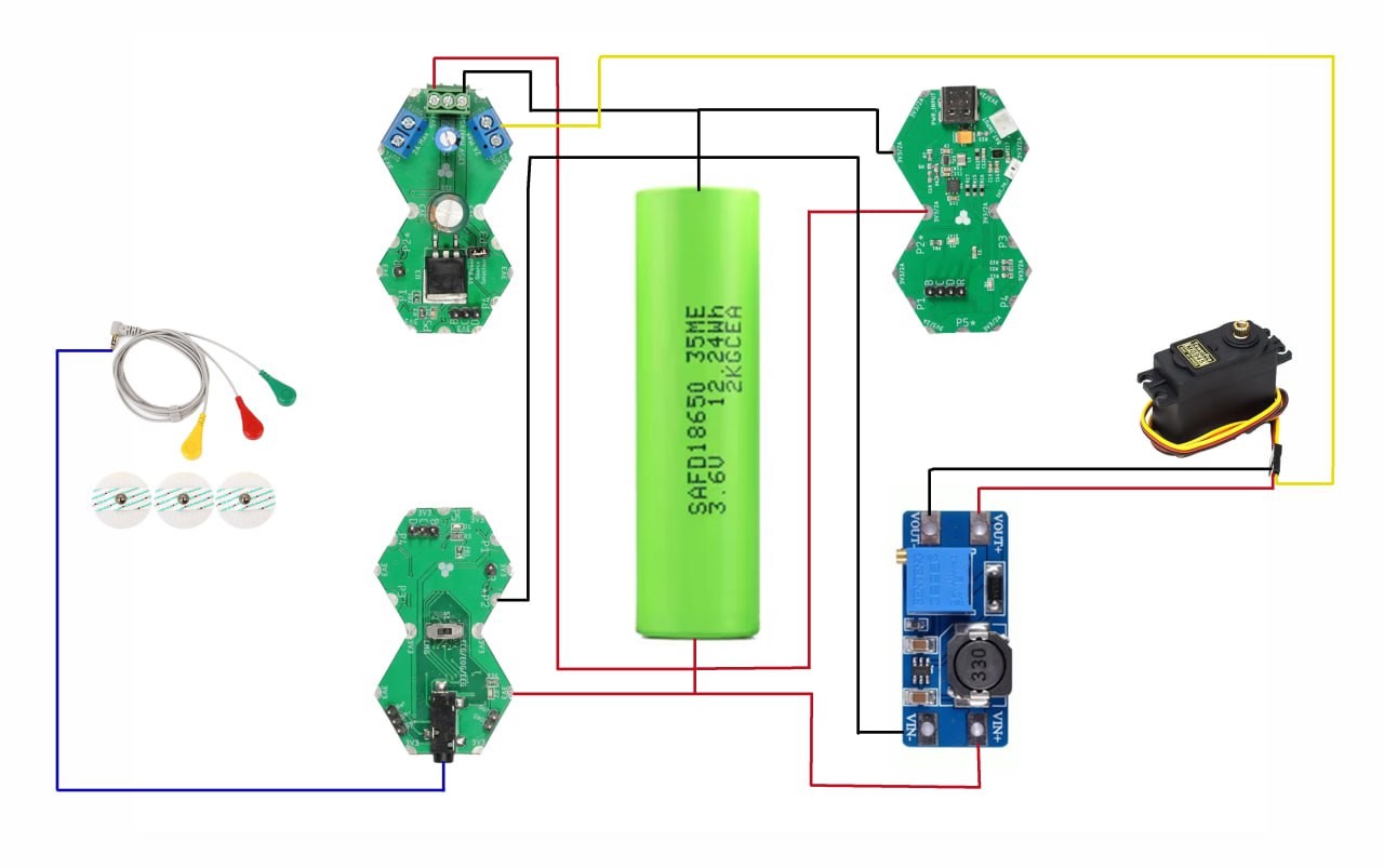
Below is the final connection diagram for the components and electronic circuits utilized:
Mechanical Section:
The design of the mechanical structure is considered the most challenging phase in the development of a prosthetic limb, as it requires taking appropriate measurements, designing the parts, 3D printing them, assembling them, and subjecting them to testing. This chapter reviews the design and manufacturing stages that were undertaken, as well as how the elements and electronic circuits were assembled and integrated into the arm.
The design should resemble a natural hand while being practical enough to assist in daily functional activities, with the hope of meeting the needs of the person with the disability. Weight must also be considered to ensure it can be comfortably carried.
Design:The design used is the Socket Version Kwawu Arm 3.0 from e-Nable. The measurements of the child were taken manually and entered into the OpenSCAD program, which then adjusted the sizes of the parts proportionately and exported them to STL files for 3D printing.
The remaining part of the injured child's forearm is 8 cm, so an upper part was designed to accommodate the child's forearm, along with a lower part that houses all the components used in the project.
It should be noted that this design is intended as a mechanical prosthetic limb. Some modifications were made using SolidWorks, where we hollowed out the interior to accommodate the necessary components for its use as an electronic prosthetic limb. An additional feature added is a small Pencil Holder piece that attaches to the palm between the index finger and thumb, allowing for the holding of a pen and writing. The wrist button piece allows for free rotation of the wrist when pressed and "locks" in place when the button is released; different wrist positions are useful when needing to carry objects.
An additional piece was designed as a base to secure the motor, battery, and electronic circuits before integrating them into the arm. This was the best option to avoid longitudinal separation of the arm for placing components, which could lead to distortion. It also facilitates making adjustments and disassembling components for maintenance if needed.
The designed parts are 3D printed, and generally, PETG is the recommended material due to its strength and solvent resistance, withstanding temperatures between 230°C to 250°C. TPU material must be used exclusively for the following parts (Hinges, Pencil Holder), which is a rubbery material that helps return fingers to their position when extended.
- Printing Standards:
• The infill percentage should be 35%.
• It is recommended that the number of top and bottom layers be 10 layers.
• Printing several small parts in one print run will reduce total printing time.
• TPU material should have a Shore A hardness range of A85 to A95.
Assembly:After each print, any excess parts from structures and edges must be removed, or if corners are rough, it is essential during assembly to avoid friction between parts. Files were used, and sanding may be necessary. All fingers are connected with a Whipple Tree piece, leading to the motor using nylon wire (fishing line) preferably rated for 80 to 120 Dyneema test strength. Super Glue is needed to secure knot locations, and epoxy is required to bond the Upper Arm to the Lower Arm. If Plasti Dip material is available, it is preferred for application on fingers to help prevent slipping while carrying objects. Additionally, some mounting screws will be necessary.
- Conclusion:
This chapter explained how to modify the design to suit the user and clarified instructions for printing and assembling parts, where 39 pieces were assembled, in addition to designing a space for placing components and securing them within the arm. The weight of the arm is less than 600 grams, which is a very suitable value. Below is the final shape of the arm after being 3D printed and assembled:
Software Section:
The final phase of the project involves writing control commands directed at the actuators. This chapter details the stages of writing the code along with the libraries used.
The code is written in C using the STM32CubeIDE environment. The code must be cleaned using the "Clean Project" option, then compiled using "Build Project" to generate a hex file. The code is then uploaded to the microcontroller using the STM32CubeProgrammer environment by clicking on the Debug icon, which initiates the ST-Link circuit to upload the code to the microcontroller. A Debug session begins to monitor the code step by step and correct any programming errors.
PWM Signal Frequency:To control the servo motor, we need to generate PWM pulses at a specific frequency. The PWM signal frequency is controlled by the following parameters:
• The value of the ARR register (Auto Reload Register)
• The Prescaler (PSC) value
• The internal clock frequency
This is expressed through the following relationship:
- Duty Cycle:
When the timer operates in PWM mode, if pulse generation is in edge-aligned mode up-counting, the duty cycle is calculated using the following relationship:
Through the 12-bit ADC of the microcontroller, analog values coming from the biosignal acquisition circuit are received and converted into corresponding digital values. The input analog voltage is calculated using the following relationship:
Where:
• ADCRes: The digital value resulting from the analog-to-digital conversion
• Vref: The reference voltage
Initially, we configure the microcontroller's inputs and outputs, define variables, and set the necessary register values for pulse width modulation.
Next, a calculation is performed for the ADC equation to adjust the desired values after testing on the injured person's muscle and measuring the signal value during muscle contraction and relaxation, in order to determine how the motor operates and the extent of its rotation angle. The process of determining and adjusting values is based on practical results and as seen fit by the designer. For this project, values were adjusted so that the wire connected to the motor would tighten and fully close the fingers of the hand upon two consecutive contractions, with a specified time interval to avoid random signals that might occur unintentionally by the user. Similarly, the motor returns to its original state upon a single muscle contraction at a value that should preferably be set within a certain range.
Difficulties:
The biggest challenge was manufacturing the outer structure, as the available space within the arm is insufficient to accommodate all the components, and the total weight of the limb must be as light as possible for the user to wear it comfortably.
Future Prospects:
• Training neural networks using artificial intelligence algorithms.
• Completely redesigning to make it more realistic by using a silicone hand.
• Increasing degrees of freedom and controlling all fingers in addition to the wrist to include additional movements.
• Replacing electronic circuits with FPGA logic chips and PIC controllers.
• Adding a force sensor on the fingers to avoid excessive pressure when grasping objects.
• Adding a temperature sensor to provide an alert in case the limb is exposed to high temperatures.
• Adding sensors that contribute to providing reflexive feedback upon touch.
• Adding a material to the fingers that allows for touch interaction on smart screens.
• Including a solar cell for charging the battery inside the arm.
• Installing a digital clock integrated with the arm.
References:
The approximate cost of this project is less than $150. If you are interested in implementing it and need consultation and assistance or have any suggestions that could help in its development, do not hesitate to contact me at: abdullah.alsaad.2001@gmail.com


_3u05Tpwasz.png?auto=compress%2Cformat&w=40&h=40&fit=fillmax&bg=fff&dpr=2)

Comments