


Hardware components | ||||||
 |
| × | 1 | |||
 |
| × | 1 | |||
RSL10-SENSE-DB-GEVK is not a beginner board. Nonetheless, I spent hundreds of hours having fun and learning while building Bluetooth® Low Energy Skydive Altimeter. In that project I showed how to display big numbers, but what if you just want small letter?
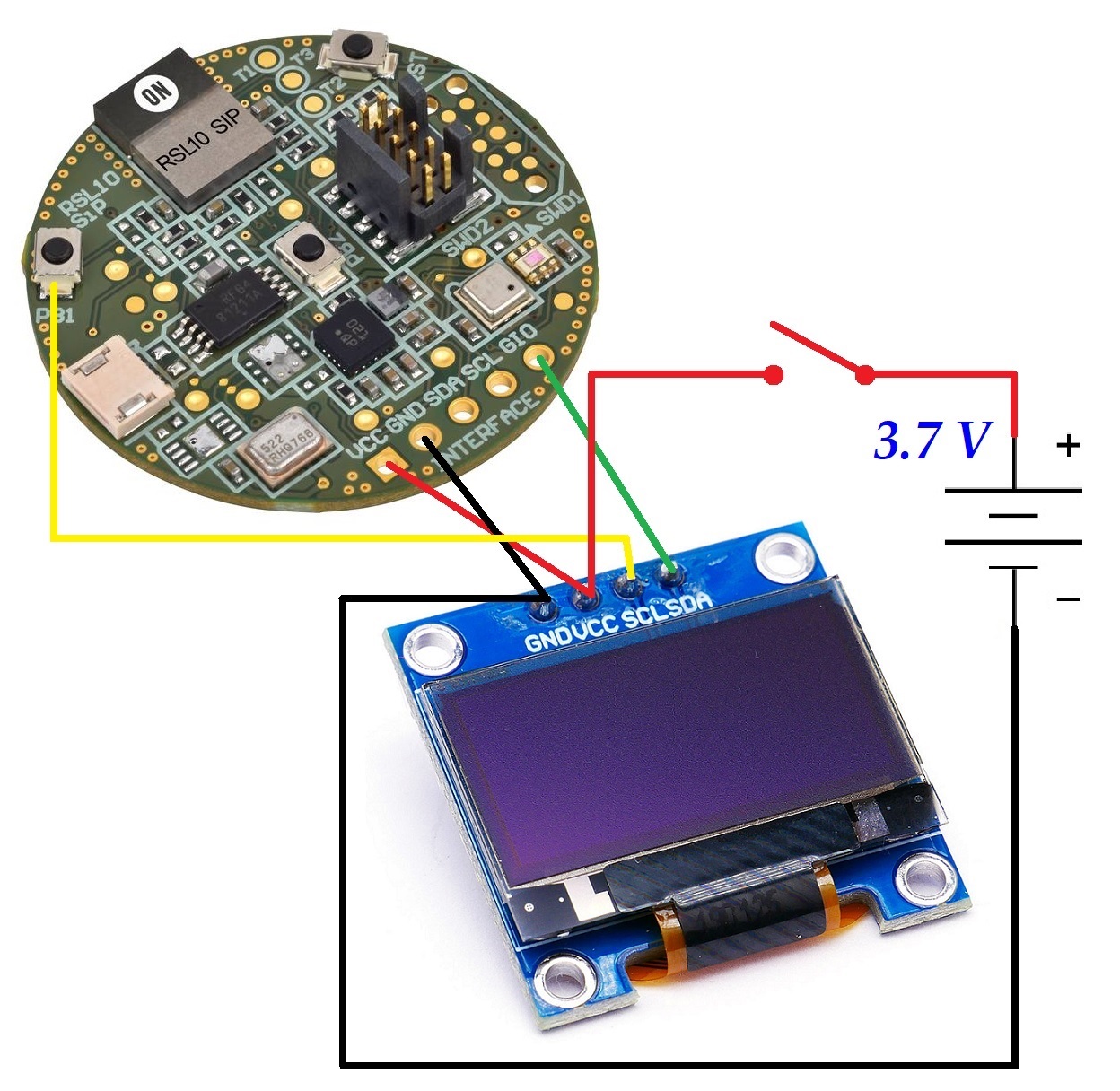
Game PlanIn this project I will use the onboard light sensor and display the results on OLED.
StepsI started with one of the examples:
Then, I added a small header file in include folder. The contents of the file as follow:
#include <BDK.h>
#define BUFFER_SIZE 64*128/8
uint8_t oled_buffer[BUFFER_SIZE];
uint8_t TextBuffer[40];
void BitBangingFont_Init(void);
void WriteBufferToDisplay(void);
void sd1306_draw_string(int32_t x, int32_t y, uint8_t* textptr, int32_t size);
Next, I modified main.c and included the header file,
#include <BitBangingFont.h>start Bit Banging,
BitBangingFont_Init();and display on OLED:
for (uint16_t i = 0; i < BUFFER_SIZE; i++) oled_buffer[i] = 0;
sd1306_draw_string(0, 0, (uint8_t*) "NOA1305", 2);
snprintf(TextBuffer, sizeof(TextBuffer), "Illuminance: %lu lux", lux);
sd1306_draw_string(0, 20, TextBuffer, 1);
snprintf(TextBuffer, sizeof(TextBuffer), "%lu", timestamp);
sd1306_draw_string(0, 50, TextBuffer, 1);
WriteBufferToDisplay();
Finally, I added BitBangingFont.c in src folder.
Code has been uploaded to GitHub at the link below.
Please not that I'm using Bit Banging I2C because I damaged I2C pins during testing. If you still have I2C pins functioning you may want to use them instead and modify my code.
Here is the modified PinNames.h used to Bit Bang I2C:
//-----------------------------------------------------------------------------
// Copyright (c) 2018 Semiconductor Components Industries LLC
// (d/b/a "ON Semiconductor").  All rights reserved.
// This software and/or documentation is licensed by ON Semiconductor under
// limited terms and conditions.  The terms and conditions pertaining to the
// software and/or documentation are available at
// http://www.onsemi.com/site/pdf/ONSEMI_T&C.pdf ("ON Semiconductor Standard
// Terms and Conditions of Sale, Section 8 Software") and if applicable the
// software license agreement.  Do not use this software and/or documentation
// unless you have carefully read and you agree to the limited terms and
// conditions.  By using this software and/or documentation, you agree to the
// limited terms and conditions.
//-----------------------------------------------------------------------------
//! \addtogroup BDK_GRP
//! \{
//!
//! \addtogroup TGT_GRP Target
//!
//! \brief Evaluation board specific definitions.
//!
//! \{
//!
//! \addtogroup TGT_RSL10_SENSE_GRP RSL10-SENSE-GEVB
//! \{
//-----------------------------------------------------------------------------
#ifndef PIN_NAMES_H_
#define PIN_NAMES_H_
/** \brief Pin mappings used by the RSL10-SENSE-GEVK board.
*
* These DIO pad definitions are used by HAL drivers and board support libraries
* when referring to GPIO pins.
*/
typedef enum {
NC = -1,
/** All available GPIO pins of RSL10. */
PIN_DIO0 = 0,
PIN_DIO1,
PIN_DIO2,
PIN_DIO3,
PIN_DIO4,
PIN_DIO5,
PIN_DIO6,
PIN_DIO7,
PIN_DIO8,
PIN_DIO9,
PIN_DIO10,
PIN_DIO11,
PIN_DIO12,
PIN_DIO13,
PIN_DIO14,
PIN_DIO15,
/* I2C Peripheral pins */
PIN_I2C_SCK = PIN_DIO5, /**< I2C Clock signal */
PIN_I2C_SDA = PIN_DIO4, /**< I2C Data signal*/
/* SPI Peripheral pins */
PIN_SPI_SCK = NC, /**< NOT CONNECTED - SPI Clock signal */
PIN_SPI_MOSI = NC, /**< NOT CONNECTED - SPI MOSI signal */
PIN_SPI_MISO = NC, /**< NOT CONNECTED - SPI MISO signal */
PIN_SPI_CS = NC, /**< NOT CONNECTED - SPI CS signal. */
/* UART Peripheral pins */
PIN_UART_TX = NC, /**< NOT CONNECTED - UART TX signal */
PIN_UART_RX = NC, /**< NOT CONNECTED - UART RX signal */
/* Board specific pins */
PIN_RECOVERY = PIN_DIO12, /**< Pin used for deep sleep recovery in HAL. */
PIN_BUTTON0 = NC, //PIN_DIO15, /**< On-board user button PB1 (PCB edge). */
PIN_BUTTON1 = PIN_DIO12, /**< On-board user button PB2 (Board center). */
PIN_LED_RED = PIN_DIO2,
PIN_LED_GREEN = PIN_DIO1,
PIN_LED_BLUE = PIN_DIO0,
PIN_GIO_SPARE = NC, //PIN_DIO3, /**< GPIO pin for expansion header. */
PIN_INT_NOA1305 = PIN_DIO13, /**< IRQ signal from on-board NOA1305 ALS. */
PIN_INT_BHI160 = PIN_DIO9, /**< IRQ signal from on-board BHI160 sensor. */
/* ERRATA: CLK and DIO pins are swapped on mic pads */
PIN_MEMS_CLK = PIN_DIO10, /**< Clock for on-board MEMS microphone. */
PIN_MEMS_DOUT = PIN_DIO6 /**< Data input from on-board MEMS microphone. */
} PinName;
#endif /* PIN_NAMES_H_ */
//! \}
//! \}
//! \}


Comments
Please log in or sign up to comment.