Abstract
This project uses a Raspberry Pi 3 to control a 12 volt 600ma dc fan, using a transistor and diode to create an electronic autonomous switch to activate and deactivate the fan. The coding for the Raspberry Pi was written in python 2.7. The controlling factors of this code allow you to set the fan turn on temperature, how long the program will run for, and how many seconds it will wait to pulse the sensor and acquire a new temperature reading. The Sensor used, was a BMP 180 made by JBtek. This sensor records the temperature, altitude and atmospheric pressure of the area around the sensor. This data will be displayed on the Python main terminal window every 10 seconds, per given code settings, allowing you to track the temperature changes over time.
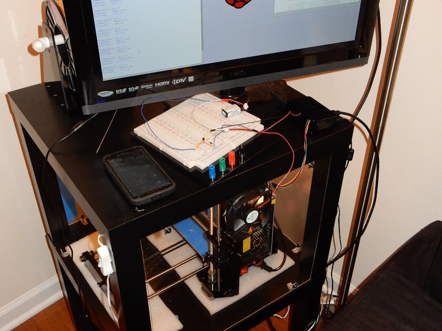
This sensor and fan project was built to record and manage the heat produced by a 3d printer in homemade enclosure to ensure a safe, and controlled temperature within the enclosure. This project should reduce the amount of temperature fluctuation and improve the quality of the 3d prints by reducing the effects of inconsistent plastic shrinkage during the print job. It will also help improve the cooling to the printer electronics and reduce the risk of the circuitry overheating.
The Problem:
3d printers get hot. This is necessary for the plastics to be able to be extruded, however too much heat, or too little can lead to plastic warping, and ruining a prototype part. The answer? Enclose the printer in a relatively air tight box that helps maintain the temperature, and then use a temperature controlled fan to regulate airflow and maintain a stable printing environment for the rapid prototyping machine.
The Circuit
This circuit uses a Bosch BMP 180 temperature sensor that was designed to measure temperature, altitude and atmospheric pressure for implementation in cell phones, handheld gps systems and general outdoor sensor devices. It runs off of 3.3v supply and uses the I2C interface. (Data sheet for BMP 180 https://cdn-shop.adafruit.com/datasheets/BST-BMP180-DS000-09.pdf )
The transistor used was a 2N3904 NPN transistor, and the diode was a 1N4001 Diode, which both come in the Sparkfun beginner parts kit. The resistor you chose will depend on the power supply you use and the fan amperage you select.
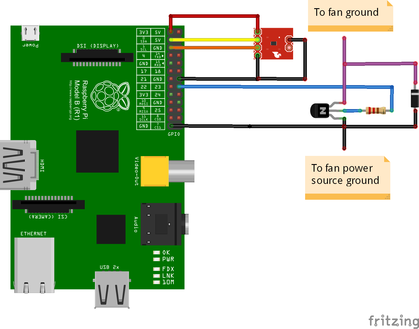
For each measurement cycle, the sensor gathers temperature data, and then begins pressure measurement. Once data is gather the sensor will format the data into a usable form (Celsius and hPa) and will transmit the temperature, pressure, and calculated altitude based on air pressure to the Raspberry Pi. The Raspberry Pi will then analyze this data with python software and determine if the fan should be turned on or not. If turned on the Raspberry Pi will send a signal to the Transistor which will in turn allow the power source (battery) to power the fan. The actual circuit is show below.
The Code
For this project, I used python 2.7, as the base code for interpreting the sensor signals was written in python. Since this sensor uses several sensor specific files, you have to download them from the internet to setup your Raspberry Pi. The instructions for setting up your Raspberry Pi for using GPIO, I2C, and the BMP Library are linked to below
1) Setup Kernal support for I2C
https://learn.adafruit.com/adafruits-raspberry-pi-lesson-4-gpio-setup/configuring-i2c
2) Install Python and python-rpi.gpio (GPIO Capability)
https://learn.adafruit.com/adafruits-raspberry-pi-lesson-4-gpio-setup/configuring-gpio
3) Install Adafruit BMP Python Library (page 9)
https://learn.adafruit.com/downloads/pdf/using-the-bmp085-with-raspberry-pi.pdf
Now from the Adafruit BMP Python library, change directory into the examples folder (cd examples)
and use sudo python simpletest.py to test sensor. if you receive an output, then your sensor is working properly!
Python Code
Once you have your fan connected to your circuit, you can test the connection with the turn_fan_on.py and turn_fan_off.py code provided (see attachments). If this works then you can proceed to the Temperature Control and Display code.
In the code you will see the following varables:
Timesup: this variable controls how many seconds the program will run. It is initially at 1 hour run time.
Tfan_on: this variable is the temperature in Celsius at which the fan will turn on. You can adjust this to anything you want.
FREQUENCY_SECONDS: This variable controls the frequency of sensor pulsing. It is defaulted to 10 seconds.
Run the Code
Once you have set your preferences, you can run the program on the python module on the Raspberry Pi!
Errors and Uncertainties
This sensor has a specified manufacturer error of .1 degrees Celsius, however fluctuation of actual temperature could happen as this enclosure environment is not a perfect flow path for air, leaving hot spots and dead zones for air travel. This could throw off the data calculation. Pressure sensor also seems very sensitive to movement, it will be watched in the future for variation in pressure from the vibration of the rapid prototyping machine, and see if it needs to be mounted on a vibration dampened mount.
System Limitations
This is a very simplistic system, and does not allow for variable speeds of the fan. The data collection system is rudimentary and must be saved manually if desired. This system also only gives temperature in one specific place with one specific sensor. Multiple sensors at various places around the enclosure could increase overall temperature accuracy.t
Commercial Value
This system was relatively cheap and easy to implement, and has application for overflow valves, refrigeration units, air conditioning units, as they all react on a simple trigger of a sensor recording a specific value of heat that shouldn't be surpassed or dropped below. This is a sense a very rudimentary thermostat.
Things Learned and thought on improvement
For the future I would like to improve this system by exporting the temperature data to a spreadsheet so that it can be graphed over time. If possible I would like to export this data to a Google drive spread sheet so that i can be updated live and I can watch progress from afar. I would also like to add a fire warning sensor that messages my phone using the If this then that website to alert me of alarming temperature measurements well above normal operating temperatures. I would also like to improve the code by making the raspberry recognize the sensor at startup and boot immediately into the python program so that it does not require a keyboard and mouse setup.
This project was a learning experience on several different levels. Learning to code Python was a challenge, but it proved to be a very simple language to use for this project. I learned that transistor definitely make easy to use on/off switches that can switch on and off power supplies and devices, making autonomous control of devices very easy.
-This post was made by Alan Hilliard, as part of a project for the MEGR 3171 class at UNCC on 4/19/16


Comments
Please log in or sign up to comment.