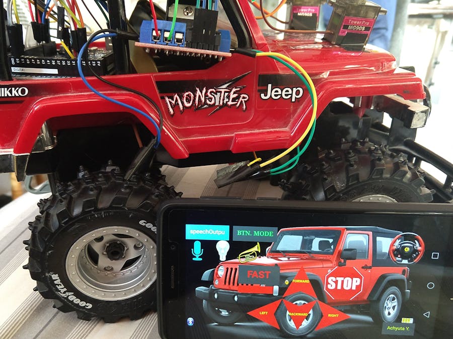
The goal of this project is to create wireless communication with an RC car using cell phone Bluetooth communication. By using a phone, one can avoid the frustration of misplacing the remote (which has happened to me on multiple occasions). Also, the phone app allows for customization of the car's control. I used MIT app inventor to create an app which allows multiple modes of operation and functions for the car, such as tilt mode, voice mode, and button mode which I will go into more detail later.
Sample video of acc mode: https://drive.google.com/file/d/1UDmx4STJnwceMz9vrOowHQuren9npsEi/view?usp=sharing
Sample video of select buttons: https://drive.google.com/file/d/1vA-XSwN3bF94aK7IaoDo5eBVYRLjmP7r/view?usp=sharing
The first step to take is to obtain any RC car with a 2 wheel drive (the front two wheels for steering). Now, we have to take off the car's outer frame in order to reach the two motors. This can be done by unscrewing a few screws here and there. Once you have taken off the plastic material, identify two wires leading out of each motor. These will be found soldered to a PCB, typically in the middle of the car. Use a wire cutter to cut of these wires (4 total) and then, as needed, extend them by soldering more wire to their ends. If desired, the frame can be screwed back onto the car, but make sure the four wires are accessible.
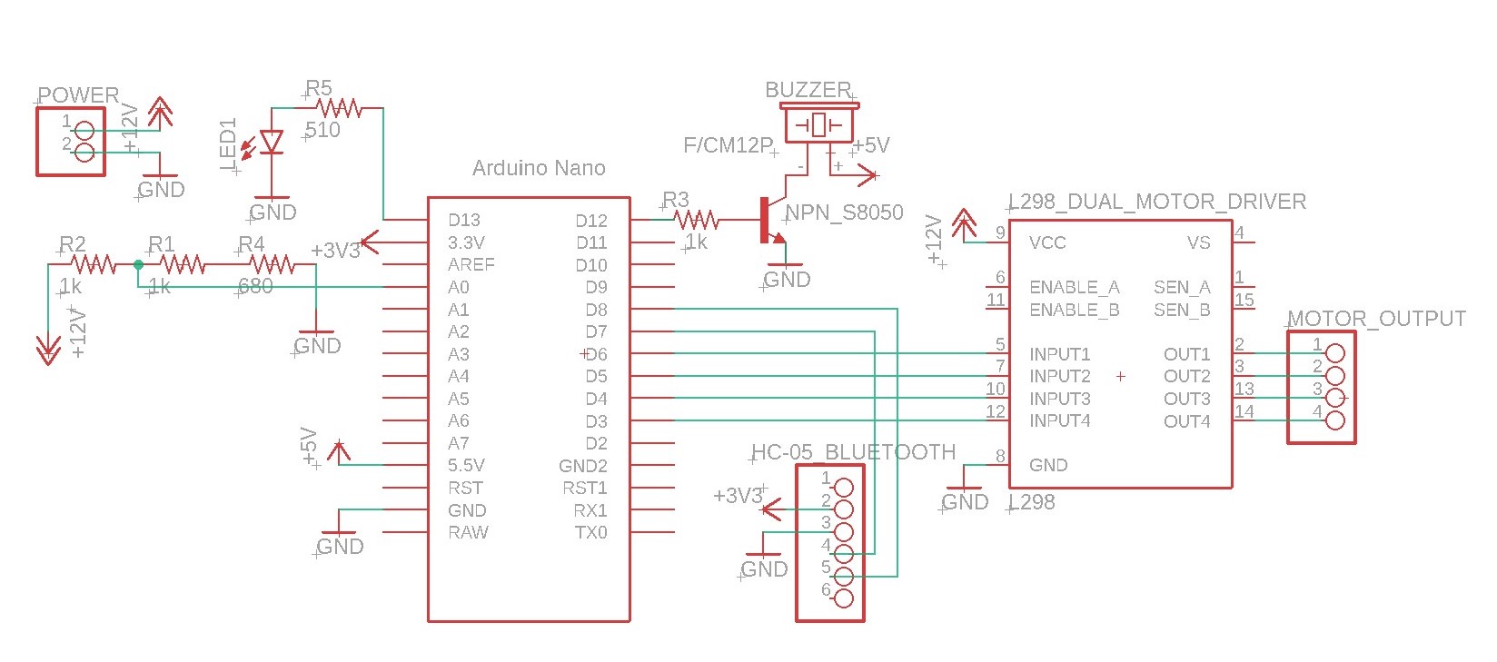
The motor driver I used is the L298 dual motor driver. The VCC and GND pins are connected to positive and negative terminals of the battery respectively. The voltage of the battery I used is around 8 Volts (2 li-ion 3.7 Volts 9900 mAh). To determine the voltage of the battery needed, check the car's voltage rating, and use a voltage slightly higher than that value. The 4 input pins for the motor driver are connected to Arduino output pins. These pins must be PWM (pulse width modulation) pins so that different speeds between 0 and 255 can be generated, not just high or low. The 4 output pins of the motor driver are connected to the two motors (pins 1 and 2 to motor 1/ pins 3 and 4 to motor 2). When testing, if the car goes opposite directions or turns when it should be going forward, simply change the pin numbers for the motors on the Arduino code.
The Bluetooth module I used is HC-05 module. It allows for data being both sent and received (master and slave modes, but only one mode communication at a time). This module is the key part to allow for communication between a phone and the RC car. For wiring, VCC and GND are connected to 3.3 Volts and GND respectively, while Tx and Rx can be connected to any digital pins (which need to be altered in the Arduino code). When initially pairing the HC-05, the password will be 1234. The buzzer and light can be connected as shown in the schematic, or with similar pins based on the Arduino board.
The app I used to control the car was created using MIT App Inventor. This is a free online program with a simple to use drag and drop interface. There are many tutorials on YouTube if you wish to create your own personalized app. The basic operation of this app is that the user pressed a button or conducts a specific action using their phone. Based on that action, the Bluetooth sensor from the phone send out a specified number to the RC car's Bluetooth module. Now, the Arduino code processes this number, and carries out a specific task (turn left for example). My app has three basic modes: button mode, tilt mode, and voice control mode.
Button mode is the simplest. It has the up/down/left/right movement buttons, as well as the stop button and speed control. Tilt mode is my favorite. It is activated using the steering wheel button in the top right of the screen. In this mode, you can control the car by tilting your phone forward, backward, left, or right to go that respective direction. By holding the phone in a neutral position, the car is stopped. This mode utilizes the phone's accelerometer's X and Y axis data in order to determine which action to take. For this mode to work best, screen autorotate must be turned off. The voice controlled mode allows you to use Google's speech to text in order to move the car. You can say actions such as "forward" or "buzzer on" in order to invoke to appropriate response. Yet, this mode is hard to use, particularly in houses. It takes a decent amount of processing time before a command is executed, and the car often has already crashed.
The other buttons on the screen are the buzzer and LED which activates these two components. In the bottom left is the Bluetooth button, which is the first step taken once the app is opened in order to establish a connection with the Bluetooth client. In the bottom right is the battery indicator, which is determined through a voltage divider shown in the schematic.
The link for the app project on MIT App Inventor is ai2.appinventor.mit.edu/?galleryId=6737895030915072. Upon opening the link, download an apk file and place this in the download folder of your phone. Then install the app, granting all the permissions needed.
For fun, I attached the.stl file for a steering wheel which I created such that you can put your phone and make the control of the RC car in tilt mode more enjoyable. The dimensions of the wheel can be modified in the 3D print software to allow for compatibility with different phones.
The Arduino code and schematic is specific to my car setup, but the pins can be easily changed as long as the code is modified as well. I am still working on this project looking for ways to improve and fixing a few of the bugs. Please let me know any suggestions or if there needs to be any clarifications.


_ztBMuBhMHo.jpg?auto=compress%2Cformat&w=48&h=48&fit=fill&bg=ffffff)


_3u05Tpwasz.png?auto=compress%2Cformat&w=40&h=40&fit=fillmax&bg=fff&dpr=2)
Comments
Please log in or sign up to comment.