


Hardware components | ||||||
_ztBMuBhMHo.jpg?auto=compress%2Cformat&w=48&h=48&fit=fill&bg=ffffff) |
| × | 1 | |||
| × | 1 | ||||
| × | 1 | ||||
| × | 1 | ||||
 |
| × | 1 | |||
| × | 1 | ||||
 |
| × | 1 | |||
 |
| × | 1 | |||
Software apps and online services | ||||||
 |
| |||||
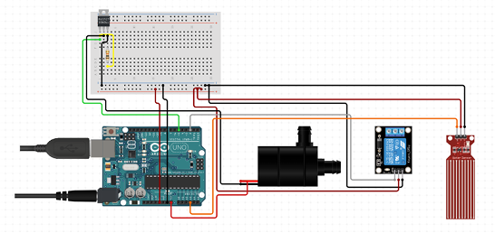
Block Diagram
Block Diagram:
- Water Level Sensor detects the water level in the bowl.
- Arduino receives data from the water level sensor and processes it.
- Relay Module receives signals from the Arduino and controls the Water Pump.
- Water Pump activates to fill the bowl when the water level is low.
- Power Supply provides energy to the system.
Water Level Sensor:
- VCC connects to the 5V pin on the Arduino.
- GND connects to the GND pin on the Arduino.
- Signal Pin connects to an analog pin (e.g., A5).
- Water Level Sensor:VCC connects to the 5V pin on the Arduino.GND connects to the GND pin on the Arduino.Signal Pin connects to an analog pin (e.g., A5).
Relay Module:
- VCC connects to the 5V pin on Arduino.
- GND connects to the GND pin on Arduino.
- IN Pin connects to a digital pin (e.g., D3) on Arduino.
- COM connects to the positive terminal of the water pump.
- NO (Normally Open) connects to the positive side of the power supply.
- NC (Normally Closed) is unused in this setup.
- The negative terminal of the water pump connects to the negative terminal of the power supply.
- Relay Module:VCC connects to the 5V pin on Arduino.GND connects to the GND pin on Arduino.IN Pin connects to a digital pin (e.g., D3) on Arduino.COM connects to the positive terminal of the water pump.NO (Normally Open) connects to the positive side of the power supply.NC (Normally Closed) is unused in this setup.The negative terminal of the water pump connects to the negative terminal of the power supply.
Water Pump:
- Connect to the relay module as outlined above.
- Water Pump:Connect to the relay module as outlined above.
Power Supply:
- Use a 9V battery or a DC power supply to power the Arduino and the pump.
- Power Supply:Use a 9V battery or a DC power supply to power the Arduino and the pump.
- Connect the Components: Set up the circuit on the breadboard, ensuring all connections are secure.
- Upload the Code: Use the Arduino IDE to upload the code to the Arduino.
Power the System: Connect the power supply and monitor the system's behavior.
- Test the water level sensor: Check if the sensor detects the water level accurately.
- Test the relay and water pump: Ensure that the relay module activates the water pump when the water level is below the threshold.
- Power the System: Connect the power supply and monitor the system's behavior.Test the water level sensor: Check if the sensor detects the water level accurately.Test the relay and water pump: Ensure that the relay module activates the water pump when the water level is below the threshold.
- Adjust the Water Level Threshold: You can modify the
waterLevelThresholdvalue to suit your specific needs (i.e., how high or low you want the water level to be before activating the pump). - Debugging: Use the serial monitor in the Arduino IDE to view real-time readings from the water level sensor and ensure proper operation of the pump.
- Enclosure: Place the components in a protective enclosure to prevent damage and ensure safety for pets.
- Pet-Friendly Design: Ensure there are no sharp edges or easily detachable components that could harm pets.
- Test Again: Perform final tests to ensure that the system works as expected in a controlled environment.

3 projects • 1 follower
I'm a Computer Engineering student passionate about hardware-software integration, data analytics, and embedded systems.
Thanks to Jamaica Kaye Lopez, Mark Joshua Rodil, Carlos Miguel Marabe, and Peter Arellano.


Comments
Please log in or sign up to comment.