


Hardware components | ||||||
 |
| × | 1 | |||
 |
| × | 1 | |||
| × | 1 | ||||
Software apps and online services | ||||||
| ||||||
With the hardware demonstrated as capable of driving the selected MIPI camera, the next level of development is on testing the algorithms which will be deployed.
Of course, it is often the case the we want to use high level frameworks such as OpenCV etc. these algorithms can be developed using OpenCV on desktop machines. However development on desktop machines has some limitations as the input images or video are not provided by the actual camera sensor.
Being able to use the real sensors enables the algorithms performance to be more accurately determined. Running PYNQ on the Ultra96V2 enables us to develop a custom overlay which works with the PCAM 5C sensor. Using this overlay we can then also use OpenCV to test develop and test our algorithms.
Of course these algorithms, will be running on the processing system so the performance will not be the same as if accelerated into the programmable logic.
Creating the OverlayWe can use the Vivado design created in part one as the basis for the overlay, we do not need to make significant changes to this design inserting only two additional IP blocks which will pack the pixels in memory in a manner which the PYNQ drivers understand.
To create the overlay we first need to download the PYNQ source from pynq.io
Within this source code you will find under the boards / IP / HLS directory a number of IP along with a batch files to build them. Run the batch file suitable for your operating system, this will generate the HLS IP so they can be used in Vivado.
Once these IP cores have been generated we can add the IP repository into the Vivado project from session one.
We can then add in the Pixel Pack and Pixel Unpack IP blocks into the design
Once this is completed, we can build the image and get started to build out PYNQ overlay.
Creating the OverlayTo create the overlay we need the following elements
- Bit file for the programmable logic - this is created by Vivado and available under the runs directory
- HardWare Handoff file - also generated by Vivado and defines the configuration of the PS and the PL for the overlay. It will be available under the srcs directory in Vivado
- __init__.py - Initialisation file
- Python Class defintion - Defines the class used for the overlay
The initialization and and __init__ file can be created with a few lines of Python
Python Class
import pynq
from pynq import GPIO

__author__ = "Adam Taylor"
__copyright__ = "Copyright 2020, Adiuvo"
__email__ = "Adam@adiuvoengineering.com"


class session_2Overlay(pynq.Overlay):
    """.
    """
    def __init__(self, bitfile, **kwargs):
        super().__init__(bitfile, **kwargs)
        if self.is_loaded():
            pass
__init__.py
from .session_2 import session_2OverlayWe can then copy these four files directly into the PYNQ file system using a SAMBA connection.
We are now ready to create our Jupyter Notebook and develop our algorithms.
Jupyter Note BookWithin our Notebook we can start using OpenCV and other commonly used PYNQ frameworks to process the data from the camera. We can even get the notebook to record video of the processing as well, great from demonstrations and
As such our notebook is going to do the following stages
- Load in the overlay
- Configure the camera over I2C using the SMBus package
- Check the overlay contents
- Check the frequency of the PL clock is 100 MHz
- Configure the VDMA
- Read a frame from the camera and save it as a JPG - this proves the PYNQ chain is working correctly.
- Implement a simple object detection algorithm which tracks changes in the object and allows them to be tracked. This will also record a video of the processing algorithm
Implementing such a solution is pretty simple
from pynq.overlays.session_2 import session_2Overlay
overlay = session_2Overlay('session_2.bit')
overlay?
from pynq.ps import Clocks
Clocks.fclk0_mhz

from pynq.lib.video import *
from pynq import pl
import cv2
import matplotlib.pyplot as plt
import scipy.ndimage
import matplotlib.image as mpimg

import smbus2
from smbus2 import SMBus, i2c_msg
from pynq import GPIO

output = GPIO(GPIO.get_gpio_pin(37), 'out')
output.write(1)

i2c_bus = smbus2.SMBus(4)
Sensor_addr = 0x3c

msg = i2c_msg.write(Sensor_addr, [0x31, 0x00])
i2c_bus.i2c_rdwr(msg)

msg = i2c_msg.read(Sensor_addr, 0x1)
i2c_bus.i2c_rdwr(msg)

data = list(msg)
print("Camera ID is = ",hex(data[0]))

cfg = [[0x3008, 0x42],[0x3103, 0x03],[0x3017, 0x00],[0x3018, 0x00],[0x3034, 0x18], [0x3035, 0x11],[0x3036, 0x38],[0x3037, 0x11],[0x3108, 0x01],[0x303D, 0x10],[0x303B, 0x19],[0x3630, 0x2e],[0x3631, 0x0e],[0x3632, 0xe2],[0x3633, 0x23],[0x3621, 0xe0],[0x3704, 0xa0],[0x3703, 0x5a],
[0x3715, 0x78],[0x3717, 0x01],[0x370b, 0x60],[0x3705, 0x1a],[0x3905, 0x02],[0x3906, 0x10],[0x3901, 0x0a],[0x3731, 0x02],[0x3600, 0x37],[0x3601, 0x33],[0x302d, 0x60],[0x3620, 0x52],[0x371b, 0x20],
[0x471c, 0x50],[0x3a13, 0x43],[0x3a18, 0x00],[0x3a19, 0xf8],[0x3635, 0x13],[0x3636, 0x06],[0x3634, 0x44],[0x3622, 0x01],[0x3c01, 0x34],[0x3c04, 0x28],[0x3c05, 0x98],[0x3c06, 0x00],[0x3c07, 0x08],
[0x3c08, 0x00],[0x3c09, 0x1c],[0x3c0a, 0x9c],[0x3c0b, 0x40],[0x503d, 0x00],[0x3820, 0x46],[0x300e, 0x45],[0x4800, 0x14],[0x302e, 0x08],[0x4300, 0x6f],[0x501f, 0x01],[0x4713, 0x03],[0x4407, 0x04],
[0x440e, 0x00],[0x460b, 0x35],[0x460c, 0x20],[0x3824, 0x01],[0x5000, 0x07],[0x5001, 0x03]]

for cmd in cfg:
    #print(hex(cmd[0]))
    #print(hex(cmd[1]))
    first = cmd[0].to_bytes(2,'big')
    #print(hex(first[0]), hex(first[1]), hex(cmd[1]))
    msg = i2c_msg.write(Sensor_addr, [first[0],first[1],cmd[1]])
    i2c_bus.i2c_rdwr(msg)

awb = [[0x518d ,0x00],[0x518f ,0x20],[0x518e ,0x00],[0x5190 ,0x20],[0x518b ,0x00],[0x518c ,0x00],[0x5187 ,0x10],[0x5188 ,0x10],
[0x5189 ,0x40],[0x518a ,0x40],[0x5186 ,0x10],[0x5181 ,0x58],[0x5184 ,0x25],[0x5182 ,0x11],[0x3406 ,0x00],[0x5183 ,0x80],[0x5191 ,0xff],
[0x5192 ,0x00],[0x5001 ,0x03]]

for cmd in awb:
    #print(hex(cmd[0]))
    #print(hex(cmd[1]))
    first = cmd[0].to_bytes(2,'big')
    #print(hex(first[0]), hex(first[1]), hex(cmd[1]))
    msg = i2c_msg.write(Sensor_addr, [first[0],first[1],cmd[1]])
    i2c_bus.i2c_rdwr(msg)

res_720p = [[0x3008, 0x42],	[0x3035, 0x21],[0x3036, 0x46],	[0x3037, 0x05],	[0x3108, 0x11],[0x3034, 0x1A],	[0x3800, (0 >> 8) & 0x0F],
[0x3801, 0 & 0xFF],[0x3802, (8 >> 8) & 0x07],[0x3803, 8 & 0xFF],[0x3804, (2619 >> 8) & 0x0F],[0x3805, 2619 & 0xFF],
[0x3806, (1947 >> 8) & 0x07],[0x3807, 1947 & 0xFF],[0x3810, (0 >> 8) & 0x0F],[0x3811, 0 & 0xFF],[0x3812, (0 >> 8) & 0x07],
[0x3813, 0 & 0xFF],[0x3808, (1280 >> 8) & 0x0F],[0x3809, 1280 & 0xFF],[0x380a, (720 >> 8) & 0x7F],[0x380b, 720 & 0xFF],
[0x380c, (1896 >> 8) & 0x1F],[0x380d, 1896 & 0xFF],[0x380e, (984 >> 8) & 0xFF],[0x380f, 984 & 0xFF],[0x3814, 0x31],
[0x3815, 0x31],[0x3821, 0x01],[0x4837, 36], [0x3618, 0x00], [0x3612, 0x59],[0x3708, 0x64],[0x3709, 0x52],[0x370c, 0x03],
[0x4300, 0x00],[0x501f, 0x03],[0x3008, 0x02]]

for cmd in res_720p:
    #print(hex(cmd[0]))
    #print(hex(cmd[1]))
    first = cmd[0].to_bytes(2,'big')
    #print(hex(first[0]), hex(first[1]), hex(cmd[1]))
    msg = i2c_msg.write(Sensor_addr, [first[0],first[1],cmd[1]])
    i2c_bus.i2c_rdwr(msg)

demo = overlay.v_demosaic_0
#gamma = overlay.v_gamma_lut_0

demo.write(0x10,1280)
demo.write(0x18,720)
demo.write(0x28,0x03)
demo.write(0x00,0x81)

#gamma.write(0x10,1280)
#gamma.write(0x18,720)
#gamma.write(0x20,0x00)
#gamma.write(0x00,0x00)

pixel_in = overlay.pixel_pack_0
pixel_in.bits_per_pixel = 24

mipi = overlay.mipi_csi2_rx_subsyst_0
op =mipi.read(0x60)
print("virtual channel 0 status =", hex(op))

cam_vdma = overlay.axi_vdma_0
lines = 720
framemode = VideoMode(1280, lines, 24)
cam_vdma.readchannel.mode = framemode
cam_vdma.readchannel.start()

cam_vdma.readchannel.running
cam_vdma.readchannel.mode

frame_camera = cam_vdma.readchannel.readframe()
frame_color=cv2.cvtColor(frame_camera,cv2.COLOR_BGR2RGB)
pixels = np.array(frame_color)
plt.imshow(pixels)
plt.show()
When I ran this notebook on my PYNQ target the image below was saved
If we want to use the Ultra96V2 PYNQ capabilities to display on the Display Port monitor we can use the commands below in our Python script
framemode
vidOut=DisplayPort()
vidOut.configure(framemode,PIXEL_RGB)
frameOut=vidOut.newframe()
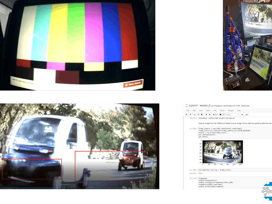
vidOut.writeframe(frameOut)The next objective was to implement the tracking algorithm, this is a very simple image tracking algorithm. It takes a reference frame at the start and then identifies any differences from the
#while True:
fourcc = cv2.VideoWriter_fourcc(*'XVID')
video = cv2.VideoWriter('op.avi', fourcc, 25, (1280, 720))
ref_frame = cam_vdma.readchannel.readframe()
ref_gray  = cv2.cvtColor(ref_frame, cv2.COLOR_BGR2GRAY)
ref_blur  = cv2.GaussianBlur(ref_gray, (5,5), 0)
for i in range(0,500):
    frame_in = cam_vdma.readchannel.readframe()
    img_gray = cv2.cvtColor(frame_in, cv2.COLOR_BGR2GRAY)
    blur = cv2.GaussianBlur(img_gray, (5,5), 0)
    difference = cv2.absdiff(ref_blur, blur)
    _, threshold = cv2.threshold(difference, 150, 255, cv2.THRESH_BINARY)[:]
    dilated = cv2.dilate(threshold, None, iterations=2)
    _, contours, heir = cv2.findContours(dilated.copy(), cv2.RETR_EXTERNAL, cv2.CHAIN_APPROX_SIMPLE)
    for i in contours:
        if cv2.contourArea(i) < 15000:
            continue
        (x,y,w,h) = cv2.boundingRect(i)
        cv2.rectangle(frame_in, (x,y), (x+w,y+h),(0,0,255),2)
    frameOut[0:720,0:1280,:]=frame_in
    video.write(frame_in)
video.release()
This will display the image tracking on both the Display Port output and record the processed video.
To test this I pointed the camera at the a tablet device which was running a video of the cars driving down the street.
The video below shows the algorithm working on the Ultra96.
Wrap UpOnce we are happy with the algorithms we have created we are able to go forward and start working on how to accelerate the algorithm into programmable logic. We will be demonstrating this part in session three of the concept to prototype.
By the completion of the second stage we have demonstrated the underlying hardware, validated and proved our algorithms using PYNQ. Good progress on our prototyping journey.


Comments
Please log in or sign up to comment.