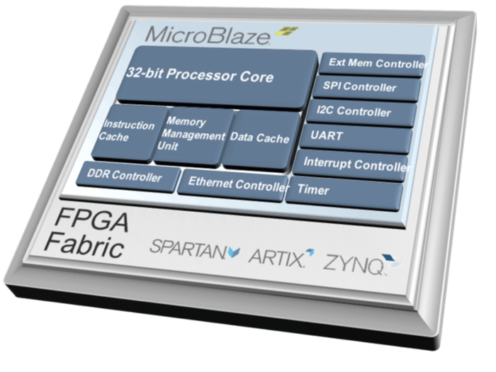
FPGA are great for implementing high performance processing pipelines or bespoke interfacing which leverage the parallel nature of the programmable logic. However, even in high performance parallel processing there are some needs for sequential processing to implement control, configuration of the processing pipeline and communication with the external world over Ethernet or UART etc.
When sequential processing is required, we have several options but the most common are the implementation of a Finite State Machine, or using a processor. FSM work well for small elements however they do not scale easily with complexity and can take a long time to debug and commission. For more complex solutions a processor can be used, in some devices (SoC) this is instantiated in the silicon while in traditional FPGA processors are implemented in the logic fabric.
In many applications the processor is deployed in the FPGA as the need for a full blown SoC is not required. In the AMD-Xilinx Eco-System the softcore processor we use is the MicroBlaze.
MicroBlaze is a Xilinx 32-bit RISC based processor which can be implemented in any Xilinx FPGA or SoC.
MicroBlaze is a 32-bit Reduced Instruction Set Processor which is scalable from a simple Microcontroller system to a real time processor and application processor capable of running Linux.
MicroBlaze is implemented using a Harvard Architecture and along with the base configurations has a range of additional interfaces and options which can be used.
In this project we are going to create a simple MicroBlaze project which is implemented in a SP701 board though most Xilinx development boards which have a LED can be used.
Hardware DesignThe first step is to create a new project in Vivado Targeting the preferred board.
Enter a name and location
Select the desired board
When the project opens, create a new diagram
Add in a MicroBlaze processor
From the board menu drag across the DDR3 Memory
Run the block automation and set the local memory to 32KB
The results of the block automation should be as below
Run the connection automation
Drag and drop the reset port onto the diagram, select the port properties to determine its polarity
Re Customize the MIG and set the System Reset Polarity for Active High
Add an AXI Timer
Run connection automation
Select the PWM Pin and Make it external
Drag the UART onto the page from the board menu
Run the connection automation
Validate the design to ensure no errors or critical warning
Create the HDL wrapper and let Vivado Manage it
Synthesize the design, once synthesis completes open the synthesized view
In the IO Ports view assign the PWM output to a pin connected to the LED
Save the constraints, and generate the bitstream. Once the bitstream is completed, export the hardware definition to Vitis.
Export the hardware with the bitstream
Launch Vitis
Select the workspace
Create a application project
Select the XSA just exported from Vivado
Enter the project name, leave the domain unchanged and select the Hello World Template.
Replace the code below in the Hello world application
#include <stdio.h>
#include "platform.h"
#include "xil_printf.h"
#include "xtmrctr.h"
#include "xparameters.h"
#define PWM_PERIOD              5000000    /* PWM period in (500 ms) */
#define TMRCTR_0                0            /* Timer 0 ID */
#define TMRCTR_1                1            /* Timer 1 ID */
#define CYCLE_PER_DUTYCYCLE     10           /* Clock cycles per duty cycle */
#define MAX_DUTYCYCLE           100          /* Max duty cycle */
#define DUTYCYCLE_DIVISOR       4            /* Duty cycle Divisor */
#define WAIT_COUNT              PWM_PERIOD   /* Interrupt wait counter */
#define TMRCTR_DEVICE_ID        XPAR_TMRCTR_0_DEVICE_ID
XTmrCtr TimerCounterInst;
int main()
{
u8  DutyCycle;
u8  NoOfCycles;
u8  Div;
u8  Value;
u32 Period;
u32 HighTime;
u64 WaitCount;
int Status;
float DivF;
init_platform();
print("Mastering MicroBlaze\n\r");
XTmrCtr_Initialize(&TimerCounterInst, TMRCTR_DEVICE_ID);
XTmrCtr_PwmDisable(&TimerCounterInst);
Div = DUTYCYCLE_DIVISOR;
Period = PWM_PERIOD;
HighTime = PWM_PERIOD * (Div/10) ;
DutyCycle = XTmrCtr_PwmConfigure(&TimerCounterInst, Period, HighTime);
/* Enable PWM */
XTmrCtr_PwmEnable(&TimerCounterInst);
while(1){
print("Select a Brightness between 0 and 9\n\r");
/* Read an input value from the console. */
Value = inbyte();
Div = Value - 0x30;
DivF = (float) Div /10;
HighTime = PWM_PERIOD * DivF;
XTmrCtr_PwmDisable(&TimerCounterInst);
DutyCycle = XTmrCtr_PwmConfigure(&TimerCounterInst, Period, HighTime);
XTmrCtr_PwmEnable(&TimerCounterInst);
}
cleanup_platform();
return 0;
}
Click the Hammer to build the App
In the Assistant window select Debug, Launch on Hardware
Open a serial terminal and resume the program using F8. In the serial terminal enter a brightness between 0 and 9 and observe the LED on the MicroBlaze get brighter or dimmer.
LED 1
LED 4
LED 9
This project has shown how to create a simple MicroBlaze project for any Xilinx FPGA. If you want to see a walked video tutorial of this and more check out the mastering MicroBlaze webinar which is available here.
You can also find step by step instructions and the slides from the mastering MicroBlaze Session below.


Comments
Please log in or sign up to comment.