This is a very long project in the making for me. You could say that it started when I ordered six endless servos in middle school, more than 15 years ago, to build a 6-axis robot arm. When I finally got them and powered them up, disappointment washed over me. They could not hold an angle... This is of course because endless servos lack feedback. I had just spent a good portion of my young self's hard earned money on the wrong kind of servos... Instead of accepting defeat and buying new servos, I decided to modify the ones I had. After countless different approaches and attempts I finally got the robot I wanted. The video below show my first 6-axis robot:
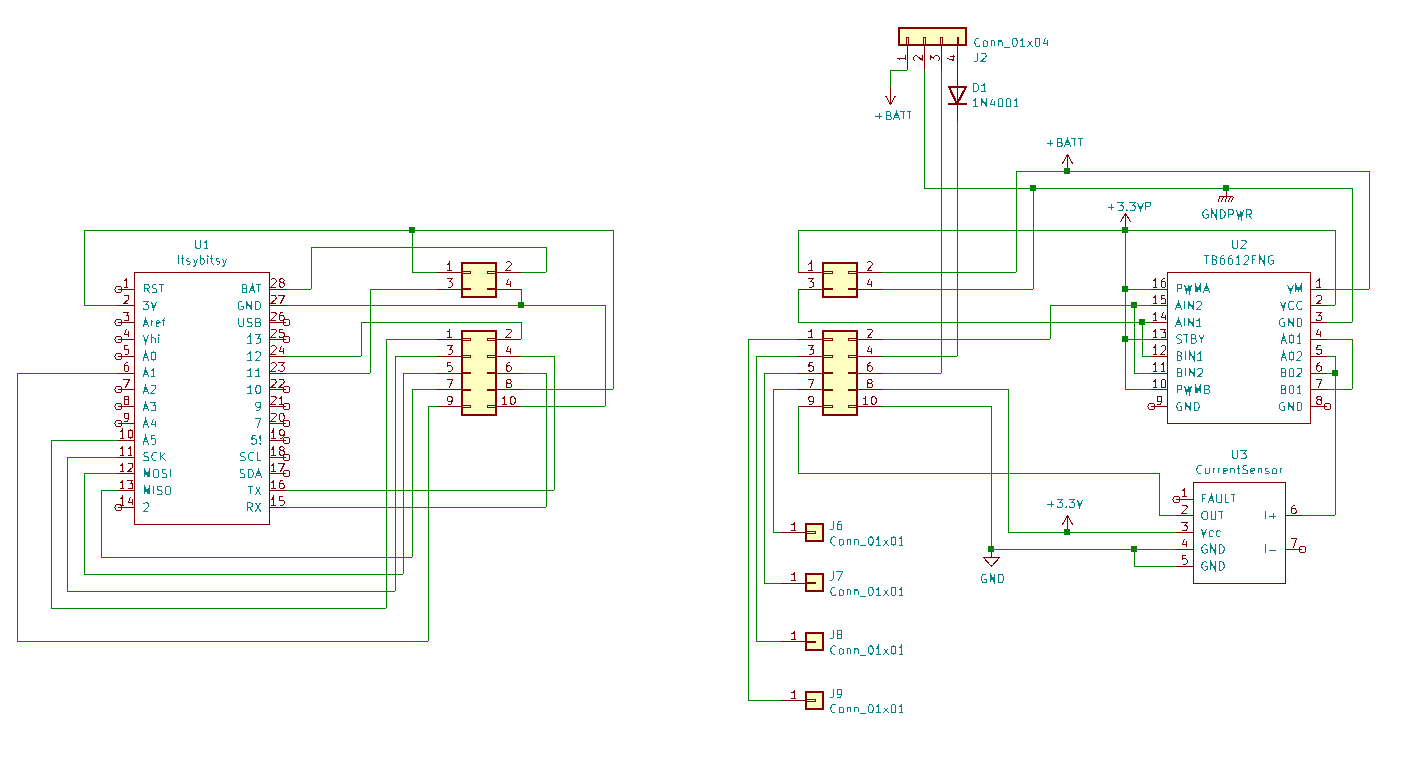
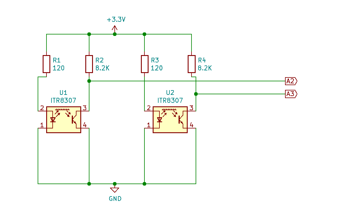
What I ended up doing was to put two reflection IR sensors in each servos DC motor, basically creating a 2-bit gray code encoder. I then used logical gates to interpret if each motor was on the right position or if the motor should turn cw or ccw to get to the right position. This worked great, but the control was very jittery since the motors were either full on or off. So I continued my quest for the perfect servo hack. And today I think I have reached something that is good enough.
TheoryThe control system of a regular hobby servo looks something like this:
This control scheme is good at holding and moving fast between position, but not so good at following a smooth predefined motion. Which is what you want when you build a robot.
Industrial servo controllers use a cascade based control scheme instead. This is the control scheme used in this project and it looks something like this:
The main benefit of this approach is that it also takes the velocity and torque into account. This allows for a much tighter motion tracking.
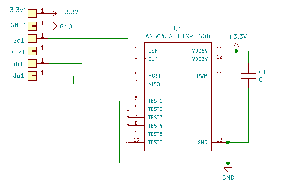
Backlash ControlWhen dealing with cheap gearboxes, backlash is always a problem. The hacked servos in this project uses two encoders to compensate for backlash. One AS5048a magnetic encoder on the output shaft and one custom optical encoder inside the DC motor. The benefit of having the extra encoder inside the motor is getting higher resolution and a main control loop which is backlash free. If one would only use the AS5048a for controlling, the backlash would enter the control loop as a time delay. This limits the control loop performance.
The backlash compensation is done by moving the main control loops reference-position so that the output encoder reaches the correct position.
Optical Encoder Inside DC MotorSee README.md in repository root for more info and step-by-step instructions
This project uses my ThreadHandler Arduino library and I have found i very useful. You can read more about it here (https://create.arduino.cc/projecthub/adamb314/interrupting-thread-handler).


_3u05Tpwasz.png?auto=compress%2Cformat&w=40&h=40&fit=fillmax&bg=fff&dpr=2)
Comments
Please log in or sign up to comment.