


Hardware components | ||||||
| × | 1 | ||||
| × | 1 | ||||
| × | 2 | ||||
 |
| × | 1 | |||
| × | 1 | ||||
 |
| × | 2 | |||
 |
| × | 2 | |||
 |
| × | 1 | |||
| × | 1 | ||||
 |
| × | 2 | |||
 |
| × | 1 | |||
 |
| × | 1 | |||
 |
| × | 1 | |||
 |
| × | 1 | |||
| × | 1 | ||||
 |
| × | 1 | |||
Hand tools and fabrication machines | ||||||
 |
| |||||
 |
| |||||
Like a lot of people, I love my dog. He joined our family in the middle of quarantine, so in order to keep him mentally and physically stimulated during lockdown (he couldn't interact with many other people outside our family), I took it upon myself to teach him some tricks! Years later, he still loves jumping up to touch my hand with his nose for a savory treat. However, I don't believe these tricks are sufficiently entertaining for him, so I decided to build a treat launcher that incorporates a mentally stimulating game and a physical component to keep him healthy.
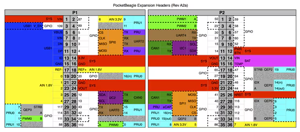
PocketBeagle PinoutThis is the pinout for the PocketBeagle development board. We will need to reference this a few times throughout the development of this project.
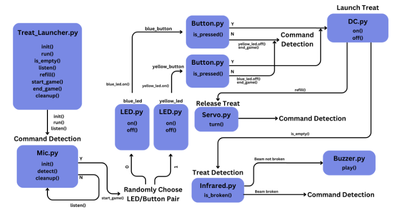
How Does it Work?So how does the project work? Please reference the software framework diagram as you read this!
Upon startup, the device will let out a playful buzz to indicate to the user that it is now listening for the activation command. The user now needs to say the command "Start the game." Your PocketBeagle needs to be connected to the internet, since the recognize_google() method that we use from the SpeechRecognition library requires the internet. Once the command has been said, give the device a moment to process your command. If it was correct, the game will start. Otherwise, it will beep again asking you to retry.
Once the game starts, a random button/LED configuration will be chosen to be active during that instance of the game. There will then be 10 seconds for the user (your dog!), to press the correct button corresponding to the lit LED. If the button is not pressed within 10 seconds, the device will reset and begin listening for the command to start. If the lit LED is pressed within the time frame, then our DC motors will start while our servo opens the treat storage and drops a treat onto the flywheel launcher, launching your dog's treat to the moon!
After the treat is dropped and launched, the infrared sensors will be polled. If the beam is not broken for longer than 5 seconds, our buzzer will start to notify you to refill the device. If the beam is broken, the device will restart the listening process.
How to BuildNow that we have an idea of how we want our device to work, let's build it! Please reference the two following diagrams.
1. Plug two jumper wires into the first and fourth terminals of the USB-A to 5-Pin Terminal Block connector. These are the GND and VCC terminals. Use a small screwdriver to tighten the terminals and secure the jumper wires into place. Plug the first terminal jumper wire into the negative power rail on either side of your breadboard and the fourth terminal jumper wire into the positive power rail on the same side of your breadboard. This will be the power source for our 5V components. Grab a black jumper wire and plug it into P1_16 on our PocketBeagle. Plug the other end into the same negative power rail that the USB-A GND terminal is connected to. This is so that our motor driver will have the same ground as the PocketBeagle.
2. Grab a red and black jumper wire. Plug the red jumper wire into P2_23 on the PocketBeagle, and plug a black jumper wire into P2_21 on the PocketBeagle. Plug the red into the positive power rail and the black into the negative power rail on the opposite side of the breadboard. This will bring 3.3V to all of our components.
3. Now, let's build our launching mechanism. For this, we will need our DV8833 Motor Driver, two DC motors, some jumper wires, our soldering iron, and some small breadboard wires. First, let's solder the headers onto our DRV8833. I didn't record myself doing it, but here's a video I found which documents the same process. Then go ahead and plug it into your breadboard wherever you feel comfortable. I went ahead and plugged it right below the PocketBeagle.
4. Now let's plug all of our wires in. Let's reference the following photos of the pinout and spinning direction logic for the DRV8833. If the sleep pin is low, our motor driver will be off. We want our motor driver to be continuously active, so connect our sleep pin to the 3.3V power rail using a breadboard wire. Connect VCC to the 5V power rail and GND to the negative power rail on the same side.
5. We want one of our motors to move forward, and the other to spin backwards. This is so we can successfully launch our objects. In order to achieve this, IN2 and IN3 to be low. Connect these pins to the GND rail closest. Our PWM signal will then go to IN1 and IN4. Grab any color jumper wire and connect it to P1_36 on the PocketBeagle. Connect the other end to IN1 on the motor driver. Use a breadboard wire to connect the PWM signal to IN4. This is so we can still start both our DC motors at the same time without cluttering our PocketBeagle with extra wires.
6. Now, our DC Motors! The ones I had didn't have wires connected to their terminals, so I had to solder them on myself. I clipped one end of one of my male-to-male jumper wires, stripped part of the wire and threaded it through the terminal. I then soldered it to secure it. Now connect one DC motor to OUT1 and OUT2, and the other to OUT3 and OUT4. It doesn't matter which is which.
7. Now, let's wire up both of our buttons. We need two push buttons, two 1k resistors, and two breadboard wires of the same size. We want an active low, configuration. Connect one terminal of the button to the 1k resistor, and then the other end of the resistor to the 3.3V rail. Then use the breadboard wire to connect the other terminal of the button to the GND rail. Repeat for the second button. Now, connect a jumper wire to P2_2 and P2_4. These will be our GPIO inputs for our buttons. Connect the green wires in series with the resistors. Connect P2_2 to the red button and P2_4 to the yellow button.
8. Now we will wire our LEDS. We need our blue and yellow LED, two jumper wires, and two breadboard wires. Connect your LEDS to the breadboard. I connected mine beside their corresponding button. We want the cathode (short side) to connect to GND, and the anode (long side) to connect to GPIO on the PocketBeagle. Connect two jumper wires to P2_6 and P2_8. These are our GPIO pins for our LEDS. Connect P2_6 to the anode of the blue LED and P2_8 to the anode of the yellow LED.
9. Add your buzzer to the breadboard. I connected mine beside my buttons. Connect one terminal to GND, and the other to the PWM pin P2_1 on the PocketBeagle.
10. Let's now connect our servo. Our servo has a three wire connector. Connect like color jumper wires to the connector.
11. Now connect the jumper wires to anywhere on your breadboard. Using breadboard wires, connect the red jumper wire to the 3.3V power rail, and the black jumper wire to GND. Using another jumper wire, connect the orange jumper wire to P2_3 on the PocketBeagle. This is for our PWM signal.
12. Now let's connect our infrared sensors. Our transmitter has one red jumper wire and one black jumper wire. Connect the red jumper wire to 3.3V and the black jumper wire to GND using breadboard wires. Our receiver has a red, black, and white jumper wire. The white jumper wire is our GPIO. Connect the red to 3.3V and the black to GND using breadboard wires. Connect a jumper wire from P1_29 to the white jumper wire on the breadboard. We want an active low config, so connect a 10k pull-up resistor from the power of the receiver to the GPIO white wire of the receiver.
13. Plug your usb microphone into the USB 4-pin adapter. Connecting our microphone is as simple as connecting VBUS to P1_7 and GND to P1_13. Make sure pin 5 and 7 on the PocketBeagle are soldered together. Make sure pin 13 and pin 15 on the PocketBeagle are also soldered together.
15. I won't go through the process of building my launcher, but here's a picture to reference for ideas.
16. Attached at the end of this hackster page is the github repo I stored all of the code that I developed. Inside the github repo is a README page under EDES301/project_01 with instructions to build the software. I'll also link the github repo right here. https://github.com/BrianoAden/EDES301/tree/main/project_01
Good luck and have fun!
How to Operate and Demo Video!Yay! You've built the launcher! Now how do you operate it?
1. On boot, the buzzer should beep notifying you that it's listening for the "Start the game" command. It may not process what you say correctly, so it might beep at you a few times asking for you to repeat yourself.
2. Once it correctly processes the command, one of two leds will light up. Your dog needs to press the corresponding button within 10 seconds.
3. If your dog fails to click the button, the game will restart. If they succeed, a reinforcement buzz will play and the servo will release the treat onto the DC motors.
4. The DC motors will launch the treat.
5. The IR sensors will now be polled, and if there isn't anything in the treat storage (the IR beam is not broken), the buzzer will begin to beep. Once the IR sensors detect a treat in the storage, it will stop and the device will listen again!
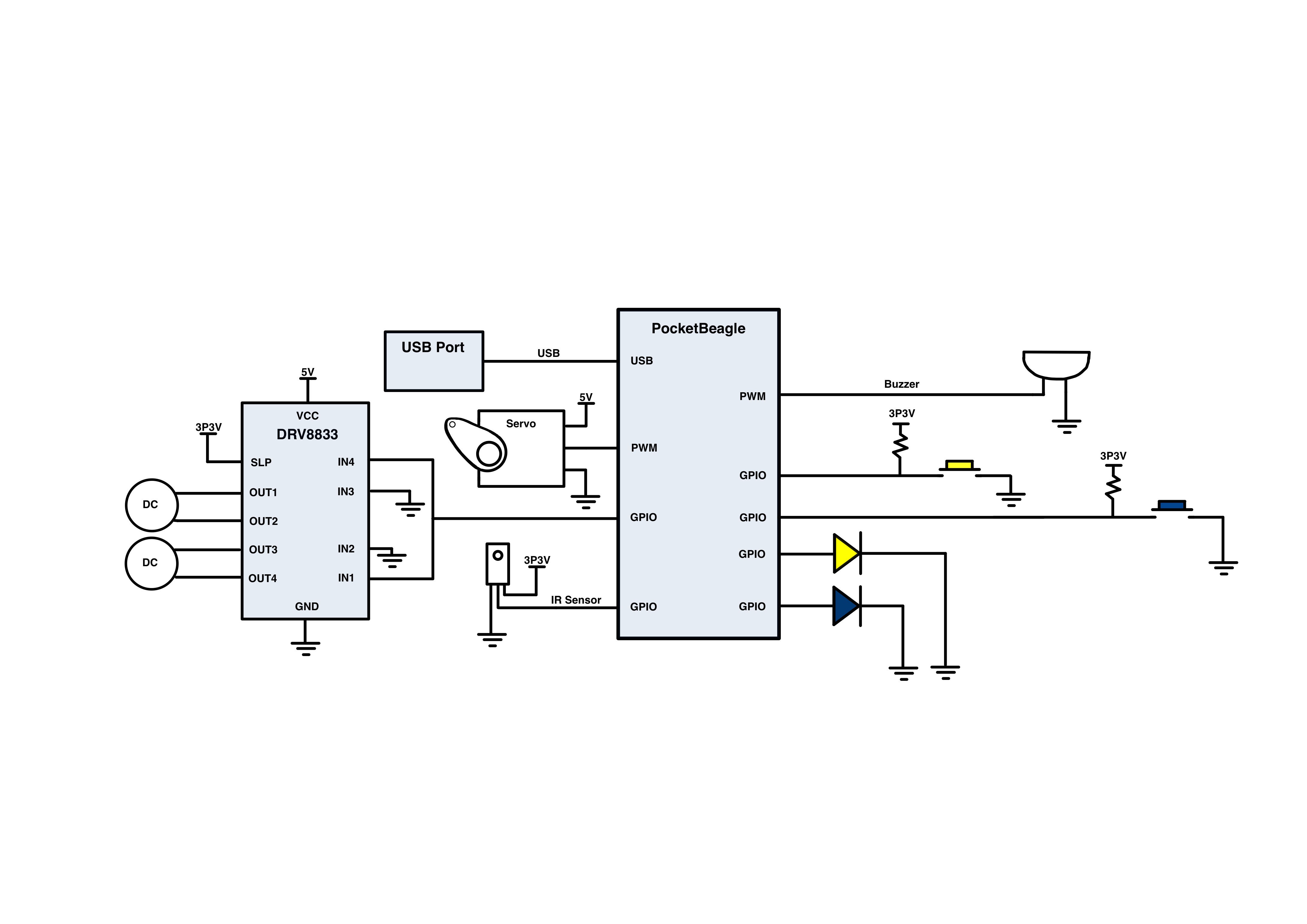
System Block Diagram
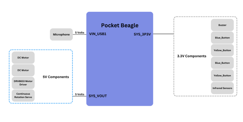
Power Block Diagram
Software Framework


_3u05Tpwasz.png?auto=compress%2Cformat&w=40&h=40&fit=fillmax&bg=fff&dpr=2)
Comments
Please log in or sign up to comment.