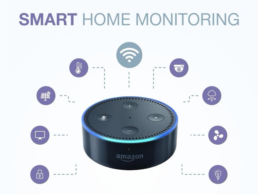
In the present world people spend more time in work place rather than their homes. Hence there is a need of home monitoring system where people can get to know the conditions of the house while they are at work. It would be even more better if one can just ask "someone" about their home during work hours. This can be accomplished by making use of Amazon Alexa as a assistant which can give the user the need information about their home.
Not Only Work Place the users can get to know the house condition at any place in the world as long as they have a internet connection and Amazon Alexa device.
The following Functions are implemented in this project:
1) Control the household Devices like fan and light
2) Tells the status of the devices
3) Tells the weather condition of the house (temperature and humidity)
4) Sends the snapshot of interior of the house to user via Gmail when required.
5) Sends notification in case of -
* Intruder ( also sends photo)
* Fire
* Guest ( also sends photo)
Steps involved in the project:
STEP 1: Programming the Arduino and ESP8266Download the Arduino IDE From the official website: https://www.arduino.cc/en/Main/Software
Open Arduino IDE and go to file-> preferences-> in additional board manager URL type - http://arduino.esp8266.com/stable/package_esp8266com_index.json
Go to tools -> boards -> Board Manager --> and install the esp8266 package found at last.
To program arduino just plug the USB cable from the arduino to computer and select Arduino/Genuino UNO in tools-> boards. Also make sure you select rights COM ports in Tools ( COM port number can be found in Device manager). Write the required Program, Compile it and click upload if there are no errors.
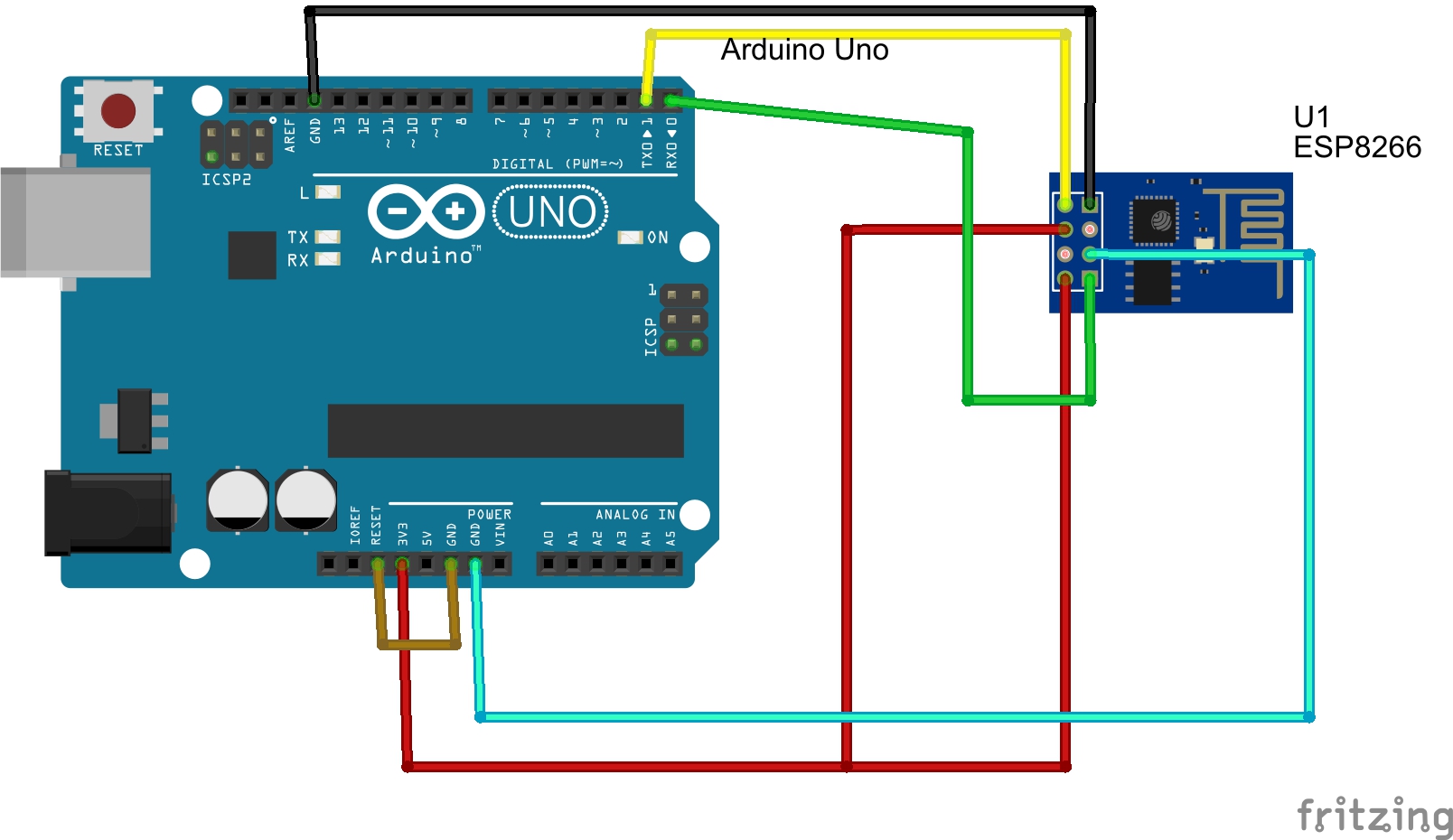
To program ESP8266 make the connection as shown in the diagram
connect the usb from arduino to Computer. In tools-> board-> select Generic ESP8266 and also select right COM port. Write the required Program, Compile it and click upload if there are no errors. Make sure you connect Arduino RST to GND (arduino acts like a programmer to ESP8266).
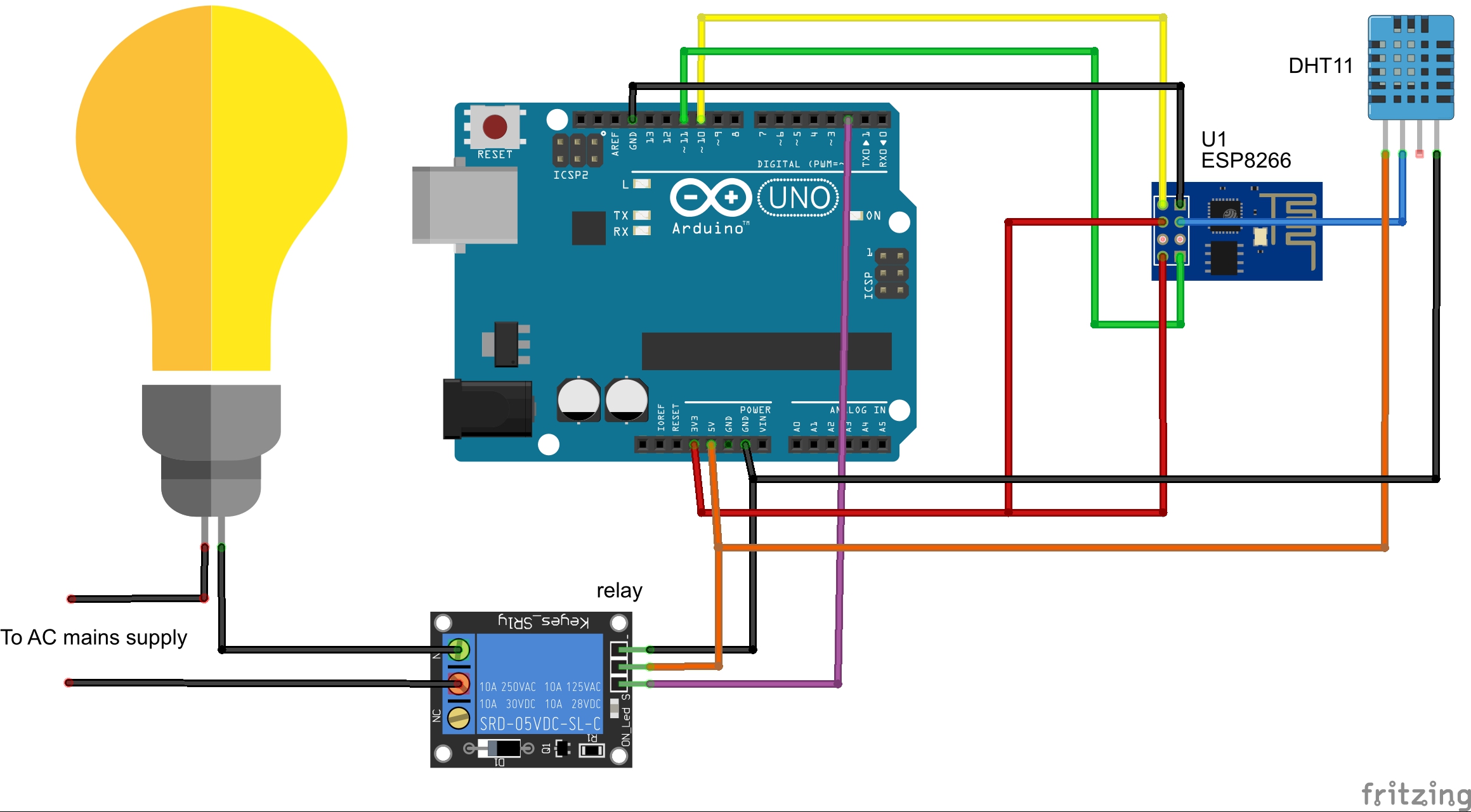
In This Project First the ESP8266 is programmed and then the circuit connections are removed. Then the Circuit is reconnected as shown in the Figure named "Circuit Connections". And then the arduino is programmed
STEP 2: Configuring thingspeak.comCreate an account in thingspeak.com.
we make use of channels in thingspeak to store the device control information and route it to arduino/alexa. we also store the temperature and humidity values in the channels. Its like a storage location for the information.
go to channels--> my channels and create new channel. Give name and description to your channels.
in our project we need 8 channels (you can do the job using less channels but it will be bit complicated while programming). Also thingspeak has a time constrain while updating a channel. There must be a gap of 10-15 sec between successive updating of a particular channel.
Eight channels with their values and meaning are given below
channel name(value1-meaning, value2-meaning, etc):
1) Device control (0 -lightON, 1- lightOff, 2- fan ON, 3- Fan Off)
2) light status (0- light off, 1- light on)
3) fan status (0- fan off, 1- fan on)
4) humidity ( value of humidity)
5) temperature ( value of temperature)
6) intruder notification (1- intruder alert)
7) fire notification ( 1- fire alert)
8)guest notification ( 1- guest alert)
when you click on any channel you can see its channel id and write API keys in the API keys tab. channel id is required to get the information/ value in the channel. and write key is required to store a value in the channel.
http request for updating a channel is :
https://api.thingspeak.com/update?api_key=<write key>&field1=<value>
<write key> is replaced by corresponding write keys of the channel and value can be (0/1 in case of device control or temp/humidity values)
http request for reading value from a channel is:
https://api.thingspeak.com/channels/<channel id>/field/field1/last.html
<channel id> is replaced by the particular channel id of the channel which we want to read from.
STEP 3: The ProgramThe program is divided into 3 parts :
A) Program for Arduino : the program for arduino is very simple. It receives the data from the ESP8266 serially and based on the data received the devices are controlled. More information about the program is found in the comments in the program itself.
B) Program for ESP8266: the program for ESP8266 involves 3 things
1) updating the temperature and humidity using http request
client.print(String("GET ")  + "/update?key=<write key>&field1="+humidity+" HTTP/1.1\r\n" + "Host: " + host + "\r\n" +
              "Connection: close\r\n\r\n");              //update humidity
 client.print(String("GET ")  + "/update?key=<write key>&field1="+temperature+" HTTP/1.1\r\n" + "Host: " + host + "\r\n" +
              "Connection: close\r\n\r\n");              // update temperature
the <write key> is replaced by the corresponding write key found in thingspeak channel for humidity and temperature respectively. and host is api.thingspeak.com.
download dht library from: https://github.com/adafruit/DHT-sensor-library
2) reading from corresponding channels of thingspeak and controlling device based on the obtained values:
client.print(String("GET ")  + "/channels/<channel id>/field/field1/last.html HTTP/1.1\r\n" + "Host: " + host + "\r\n" +
         "Connection: close\r\n\r\n");
where <channel id> is replaced by corresponding channel id found in thingspeak.
3) Sending alert in case of high temperature via pushing box
String host1="api.pushingbox.com";
client.print(String("GET ") + "/pushingbox?devid=<your dev id> HTTP/1.1\r\n" + "Host: " + host1 + "\r\n" + "Connection: close\r\n\r\n");
where <your dev id> is replaced by your device id in pushingbox.
STEP 4: Configuring linkit smart 7688 duo and webcamIn this project webcam and linkit smart 7688 duo is used to capture required photo and send it to the user. You can also use arduino camera module and interface it with arduino or use can use any IP camera.
press and hold wifi button on the linkit smart 7688 for 20 sec to reset the board. Then after wifi setting is reset you will be able to see its access point name in the wireless network connections. Now connect the computer to that network.
after you connect it open the browser and type 192.168.100.1 in the address bar. You will be able to see its portal.
set a password to login to its portal.
After you login go to network tab and select Station mode ( we need it(linkit smart 7688 duo) to access the internet) and connect it to your Wifi network and press Configure and restart.
After the board it restarted it will be assigned a local IP address. Find out the address using any IP tools or your router portal. In my case it was 192.168.1.4.
Now type the local IP address in the address bar of the browser. make sure that the computer is connected to the same network as the linkit smart. You will be asked to login again.
To enable streaming from webcam you should enable MJPG streamer(mjpg-streamer is a command line application that copies JPEG frames from one or more input plugins to multiple output plugins). To do this in the portal go to OpenWrt location in the top right. you need to login again.
After you login go to service tab and check enable MJPG streamer and assign a port number for this service. I have assigned 4440. Click save and apply.
After the setup to can connect you webcam to the linkit smart 7688 duo usb host through an OTG cable.
Now to see the Stream open the browser and type <local IP address>:<port> in the address bar. in my case it is 192.168.1.4:4400
to take the snap shot type the command <local IP>:<port>?action=snapshot
Now this image is available locally but we need to make this available to pushing box service. To achieve this we need to do port forwarding. Port forwarding can be done in router portal. The process id different for different routers. Just google to know how to port forward for for specific router. It is usually available under NAT service.
After you port forward use can access this port (ie.. 4440) from your external IP. external IP can be found by tying "whats my ip" in google.
You need to put this address ie.. http://<external IP>:<port>?action=snapshot in the pushingbox( which is explained in next step) so that pushingbox can access this image and attach it to the mail and send it to you whenever required.
You can also store the image in sd card as Linkit smart 7688 duo also comes with a sd card slot for storing information.
more information about this can be found at: https://docs.labs.mediatek.com/resource/linkit-smart-7688/en/get-started/get-started-with-the-linkit-smart-7688-duo-development-board/
STEP 5: Configuring PushingBoxpushingbox is used to send notification about different alerts in the project to gmail.
signin to pushingbox using google account: https://www.pushingbox.com/
go to my services--> add service. there are many services to choose from like Gmail, twitter, push notification for android etc...
select Gmail( as we need to send photo as attachment) and fill in appropriate gmail name configuration and gmail id of the user to whom the alert has to be sent.
go to my scenarios and create a new scenario. give name to the scenario( ex : ALERT) add the previously created service.
write suitable subject and body of the mail and enter the url to take the screenshot of web cam for attaching photo. Create different scenarios for different alerts.
api for executing a pushing box scenario is : http://api.pushingbox.com/pushingbox?devid=<device id>
STEP 6: Creating Alexa Skill using Backendlessbackendless is used to create the alexa skill. It is a simple drag and drop programming used to create alexa skill (or any programs) which can be accessed by backendless API.
create an account in backendless: https://backendless.com/
- Log in to your account in backendless account. click Create app and give a name to your app/
- Click the Business Logic icon located in the icon bar on the left. You will see the API SERVICES screen.
- Click the “+” icon to create a new service. Make sure to select CODELESS in the “New Service” popup. Enter “AlexaService”for the service name. Click the SAVE button:
- Backendless creates the API Service and will prompt you to create a method for the service. This will be the method which will process requests from Alexa. Enter “handleRequest” for the method name. Make sure to select POST for the REST operation, and declare an argument with the name of “req” and type “Any Object” as shown below:
Backendless creates a placeholder for the codeless logic of the method. Click the EDIT button to start switch to the Codeless Logic Designer.
In the created function placeholder block, click the area that says “doSomething” and change it to “sendAlexaResponse”. This function is used to make alexa say something which can be passed as argument. Click the SAVE button so the function is saved:
Click the gear icon located in the purple block right next to the word “Function”. Add two arguments by dragging the input blocks as shown in the image below. Assign the names of the arguments as “whatToSay” and “waitForResponse“. Notice that as you add arguments, the Context Blocks area is automatically populated with the blocks representing argument values:
Modify the function’s logic so it looks as in the image below. For the “Create Objects” blocks, use the gear icon to change the name of the object properties. Do not forget to save your work by clicking the SAVE button.
Now that the custom function is built, switch back to the handleRequest method of the AlexaService service. Click the Custom Functions category in the toolbar on the left and drag the sendAlexaResponse block to connect with the return connector of your service method:
the above steps can also be found in their website: https://backendless.com/developing-alexa-skill-without-writing-any-code-part1-codeless-in-backendless-mbaas/
https://backendless.com/developing-an-alexa-skill-without-writing-any-code-part2-slots/
Click the “Add New” node under Functions in the BROWSER section.In the created function placeholder block, click the area that says “doSomething” and change it to “getIntentName”
modify the blocks so that the function looks like this:
this will get the intent name based on sample utterances. Go back to api services-><app name>-->handle request in the browser section. Variables and logic is create from system section. Create the following variables:
next we store the intent name to request variable. And then compare with the intents. for example if the request is "introduction" then respond variable is set to "hi! I can control......." and this response is read aloud by alexa at last.
modify the block as shown below:
if the request is LightsOn intent then we update the thingspeak channel to '0' using http get request and at the same time we update the device status( 1/0 depending on On/Off). Same thing is repeated of LightsOff, FanOn and FanOff.
For weather we read from Temperature and humidity channel and store the result in respond variable. As the channel only give values we append texts to make the response meaningfull:
for snapshot of the living room we run pushingbox scenario:
for device status we read information from status channel of thingspeak:
for notification and alerts we read from alert channels( fire, intruder and guest):
based on the values that we get from notification field corresponding alert messages are stored in respond0 variable. if there are no notification then no notification message is stored.
once the notification is read out then the '0' is updated in the notification channels so that alexa wont read same notification again. Then at last based on the request, respond0/respond variable is read aloud.
PS : After creating the required model in backendless, click deploy model in the top right of the codeless screen to deploy the model.
STEP 7: Configuring Alexa skill in Amazon Developer Console:go to amazon developer console and signin using amazon account. https://developer.amazon.com/
go to developer console and click on ALEXA tab. Click on alexa skills kit get started.
create custom skill type, give name and invocation name to the skill.
the respective intents and sample utterances are given in the below code.
{
 "languageModel": {
   "intents": [
     {
       "name": "AMAZON.CancelIntent",
       "samples": []
     },
     {
       "name": "AMAZON.HelpIntent",
       "samples": []
     },
     {
       "name": "AMAZON.StopIntent",
       "samples": []
     },
     {
       "name": "Camera",
       "samples": [
         "please send a snapshot of my living room",
         "please send a snapshot of my home",
         "please send a photo of my living room",
         "please send a photo of my home"
       ],
       "slots": []
     },
     {
       "name": "FanOff",
       "samples": [
         "turn off Fan",
         "switch off Fan",
         "turn off the Fan",
         "switch off the Fan"
       ],
       "slots": []
     },
     {
       "name": "FanOn",
       "samples": [
         "turn on Fan",
         "switch on Fan",
         "turn on the Fan",
         "switch on the Fan"
       ],
       "slots": []
     },
     {
       "name": "Introduction",
       "samples": [
         "what you can do",
         "what can you do",
         "what can you do for me"
       ],
       "slots": []
     },
     {
       "name": "LightsOff",
       "samples": [
         "turn off lights",
         "switch off lights",
         "turn off the lights",
         "switch off the lights"
       ],
       "slots": []
     },
     {
       "name": "LightsOn",
       "samples": [
         "turn on lights",
         "switch on lights",
         "turn on the lights",
         "switch on the lights"
       ],
       "slots": []
     },
     {
       "name": "Notification",
       "samples": [
         "what are my notifications",
         "is there any notifications",
         "is there any updates",
         "read out my notifications"
       ],
       "slots": []
     },
     {
       "name": "Status",
       "samples": [
         "what is my device status",
         "what is the status of my devices"
       ],
       "slots": []
     },
     {
       "name": "Weather",
       "samples": [
         "what is the weather condition of my home",
         "what is the weather of my home",
         "what is the weather",
         "what is the temperature of my home",
         "what is the temperature"
       ],
       "slots": []
     }
   ],
   "invocationName": "my home"
 }
}
in the configuration tab select HTTPS as service end point type fill the default URL with the API URL from backendless.
select the 2nd option in Certificate for default endpoint in SSL certificate. You can also test the skill using test simulator.
After the test is complete you can publish the skill with required publish information.
STEP 8: Final setup and Finish!make the circuit connection as shown below
SometimesESP8266willmalfunctionbecauseofinsufficientcurrent.So,thoughnotmentionedinthecircuit,itisrecommended to power the ESP8266 from separate 3.3vsource.Ifyouareusingapowerbankmake sure you reduce the voltage from 5v to 3.3v using a 3.3v voltage regulator.
Upload program to ESP8266 and arduino. I have shown the connection to bulb, same thing can be extended to fan or any devices.
Finally use amazon echo or echosim.io to test you skill.
Youmustactivatetheskillusingtheinvocationname(asismycase - "myhome").Sometimesitwon'tworkifitisusedwithoutinvocationnameasIhaveshowncoupleoftimesinmyvideo.
Hope you enjoyed the tutorial!
Thank You!


_ztBMuBhMHo.jpg?auto=compress%2Cformat&w=48&h=48&fit=fill&bg=ffffff)


Comments
Please log in or sign up to comment.