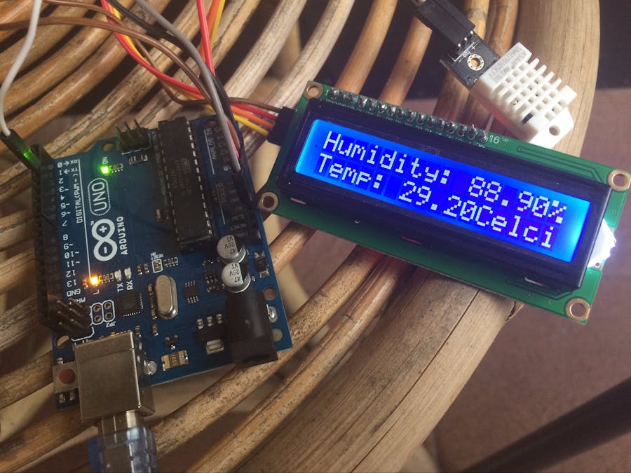
This is my first arduino project (not counting blink tutorial etc from arduino) so please bear with me..
I'm working on this after my 19MO months get coughs from our vacation, she's become very sensitive to air conditioning temperature and humidity.
The idea is creating very portable temperature and humidity sensing without making me abandon this project and carry on with finish product of temperature and humidity gadget.
In this project, I abandon breadboard because it Arduino still capable to powering sensor and LCD directly (and I don't get strangled by wires)
Hardware IntroductionArduino Uno R3
The board that i'm using is Arduino Uno R3 because it the only arduino I owned.
Uno R3 have a capabilities to powering 5v module/shield with 3v3 module/shield simultaneously so you can get rid of the breadboard for this project. Right now i'm thinking abut using Arduino Nano, I will update this project and report it.
DHT22 Temperature and Humidity Sensor
Actually there are two alternative for sensor for the first time, the DHT-22 and DHT-11 but I choose the DHT22 because it larger range for humidity and temperature, also better accuracy 0, 5% versus DHT11 1%-2%.
the DHT-22 also comes with two version, one with 4pin and the other with 3 pin. If you found yourself with the 4 pin version, you can leave the third pin from the left unused because it mean to be NC pin (not Connected)
16x2 Liquid Cristal Display with i2c Backpack
The different between i2c version with basic version is you can cut the wiring necessity to only for cable because the other was soldered to the backpack.
many store sell the i2c LCD without you need for soldering manually LCD with the backpack. the tricky parts is you need to find the port used for i2c display.
9V battery clip /holder
I also found two variant for battery holder, actually it doesn't matter which one you choose. just make sure it will fit if you make a box for this temperature monitoring.
Start your configuration with lcd first before using the DHT-22, because this LCD is a bit tricky we need to make sure it running smoothly.
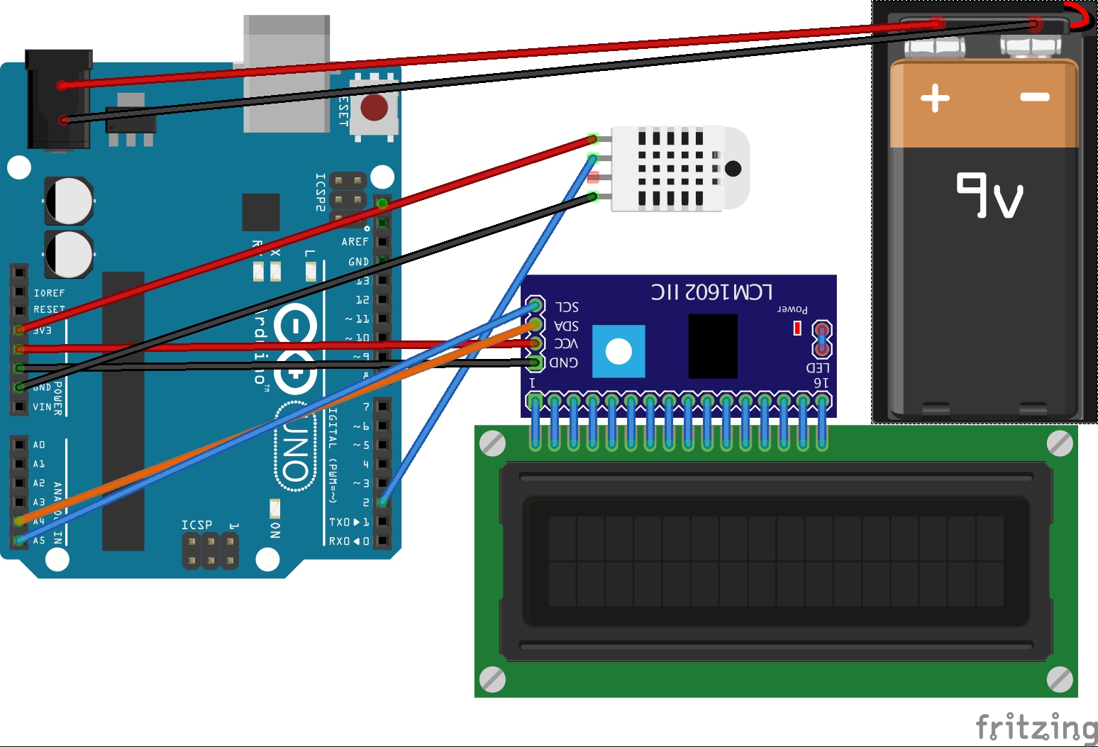
- connect SCL to A5
- connect CDA to A4
- GND to GND
- VCC to 5v
after you connect the LCD to Arduino you need to find out the address i2c using for this module. in my case the address is 0x27, some reported their address is 0x3f etc but you really test it yourself because it might different between the address i'm currently using with the one you'll be using.
I'm not gonna explain it deeper about this thing, you'll find more detailed tutorial here and don't forget to download the library because in this tutorial we're gonna using the library from that sites.
At my first attempt i've got my LCD glow without the text, If you get yourself in same situation try to rotate the contrast potentiometer first in back of your i2c (using screwdriver) if not working check also the solder between i2c to lcd especially if you solder it your self or bought from china.
Make really sure the LCD works first so it will be easier to troubleshoot the next step.
After it working we can start to the sensor part
- Connect Data Signal to D2 Arduino
- Connect VCC to 3v3 Arduino
- Connect GND to GND
Because the working voltage is 3~5v there is no reason to using higher voltage that will need to use a breadboard.
Next step is to verify, upload the sketch pull the usb, and plug the battery
If you got a problem please discuss it here, like I said before this is my first project, I hope it works for you too..
--
Note for the library: make sure the namefile you declare in sketch same with the namefile in the library.


_ztBMuBhMHo.jpg?auto=compress%2Cformat&w=48&h=48&fit=fill&bg=ffffff)


Comments