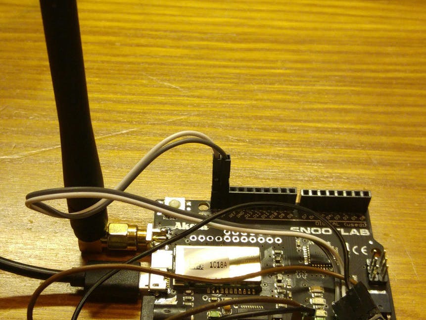
I had the chance, at Startup Weekend Lille, in 2015 February, to discover Sigfox network.
Since that, I am developing smart devices with that kind of connectivity, and which are able to send information easily, while maintaining low power consumption.
In that example, I will use this technology to show you how to use Sigfox to monitor a room temperature.
Step 1: The ProjectI decided to build a weather station, with the Akeru Board, and a BME180 sensor.
This station will upload, through the Sigfox network about every 10 minutes, 3 different values related to the sensor : temperature, humidity and barometric pressure.
It will allow to monitor the evolution of weather conditions as a 24/7 device.
In that example, we will use the Akeru board (arduino board with a Sigfox modem), but we could use Akene arduino shield, or other devices available on Sigfox makers website
Step 2: The HardwareAs you may have seen, both Akeru and Akene board use a TD1208 to ensure Sigfox connectivity.
But, rather than using this SoC as a transceiver (via an UART interface and AT commands), you can reprogram directly this SoC, because it includes an ARM Cortex M3 core, with Sigfox radio stack, and sensors capabilities through I2c, SPI ...
In fact, with Sigfox, you can either use a "simple" transmitter via a UART or I2C link to just make AT commands for communications, from your "core" (ATMega, MSP430, ARM Cortex M ...). There is transmitters at TI, Atmel, Axsem ...
Or, you can use a SoC, which is basically a module which includes an ARM Cortex M (for low power consumption) and a Sigfox radio transmitter. There is SoC from Adeunis, Atim, Telit, Telecom Design (TD1208) ...
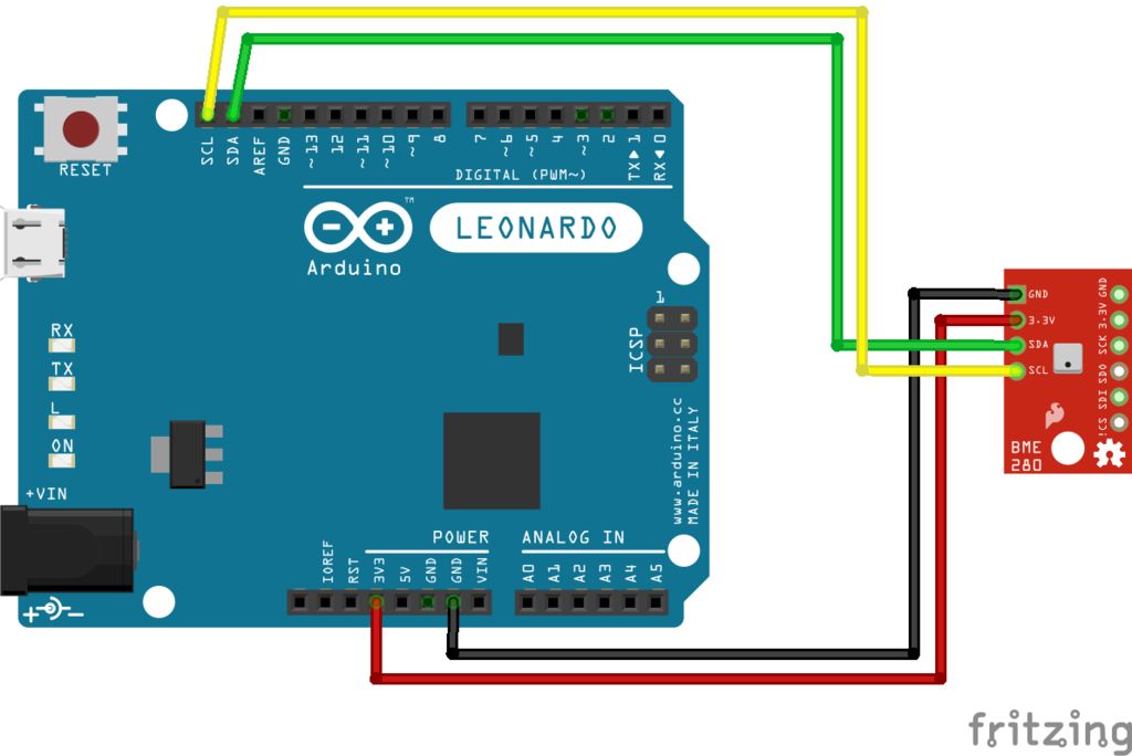
Step 3: Akeru Board and BME280 SensorThat board will look like a regular Arduino Uno in the Arduino IDE, but, installing akeru librairies, it will unleash Sigfox connectivity abilities.
I just plug my sensor as a regular I2C device, and I adapt the code to make a sensor capture and a Sigfox transmission every 10 minutes.
The • Ground to Ground (Black wire)
• 3.3v to 3.3v (Red wire)
• SDA to SDA (Green wire)
• SCL to SCL (Yellow wire)
Step 4: Sketch and Running PrototypeI just plug my sensor as a regular I2C device, and I adapt the code to make a sensor capture and a Sigfox transmission every 10 minutes.
When you upload the sketch in the Arduino IDE, you can directly open the Serial monitor to see what's going on.
In the following picture, you can see sensor data, and then Sigfox transmission, and finally sleep time of 10 minutes before an other sequence.
Step 5: Getting Values from SigfoxAs soon as you send data from your device through Sigfox network, and after few seconds you will see your data on your API provider, either Sigfox Backend, or Actoboard if you register your Akeru device on it.
Once you check on the backend you transmit correctly your data, you can configure a callback in order to store data on your server.
To do so, click on Device Type and then select the right Device Type matching your device, and then in the callback tab (at the left), you can add a callback to your url with parameters such as device, time, data ...
You can build a simple api, decoding the data (it is hexadecimal coded, handle by pair of digit), see Nicolas github for examples.
Step 6: What's Next?Congratulations, you just have build your first Sigfox powered device !
Now you can make any prototype you want (thanks to versatility of Arduino with thousand of sensors).
If you want to go deeper to know this technology, you can study modules and transmitter datasheet, in order to integrate Sigfox to your existing electronics, or build the next revolutionary thing !
adrien3d


Comments
Please log in or sign up to comment.