Although the ESP8266 01 WiFi Module has a wide support and a good community crowd, the Arduino Uno board takes advantage of it's ease of use and beginner-friendly layout over Arduino Micro for being one of the most used boards for cheap IoT solutions. As a result, there aren't many tutorials documenting how to use the module with this board. So here's a short & simple tutorial for people getting started with IoT and want to use the Micro+ESP01 combination.
Step One: PreparationFirst of all, note that the module runs at 3.3V logic. Any amount of potential difference greater than 3.5 volts can cause serious damage and may even cause some smoke to come out. I haven't tried nor would I recommend doing this but be assured that once out, that smoke is never going back in.
The module is also, no friend to your breadboard. So either you can use male to female jumper wires or make an adapter like I did.
Simply, cut 2 pieces each of male and female headers having 4 units and press the male header pins on a flat surface so the stack comes down, then solder them on a general purpose PCB. Make sure not to short anything.
Step Two: Other PartsYou'll also need an Arduino Micro or Leonardo or any Arduino compatible board that has an ATMega 32u4 processor. This is so, because we'll be using two Serial Communication ports: one is reserved for the communication between Arduino and the COM port of your laptop and the other is for the communication between the ESP module and Arduino.
Arduino Uno can be used with Software Serial Library or you can use Arduino boards that have 2 or more Serial Communication ports. I haven't tried either of them but if you have, let me know in the comments below.
The ESP Module should have the Ai-Thinker firmware or the ESP AT 1.7.4.0 firmware in order to control it via AT Commands. If you don't have it installed, you can follow the guide below and carry out the installation:
AI-Thinker AI-Cloud Inside ESP8266 Update Firmware(REVIEWED) - Arduino Project Hub
Espressif System's official tools, firmware and documentation.Step Three: Circuit Schematics
Optionally, you can also connect a push button to the RST pin of the ESP Module and the GND pin, which will act as a reset button.
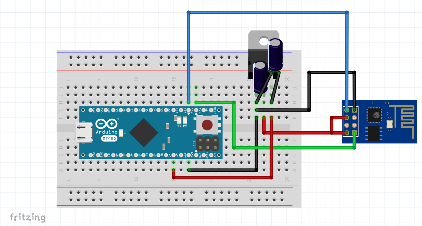
There are two communication ports available on the Arduino; Serial interface is reserved for communication between your computer (Serial Monitor), so, we'll use Serial1 interface to communicate between Arduino and ESP 01 module. The connections are pretty simple:
- RX of ESP-01 goes to TX of Arduino Micro
- TX of ESP-01 goes to RX of Arduino Micro
- GND of ESP-01 goes to GND of Arduino Micro
- VCC of ESP-01 goes to 3.3VVout pin
It's recommended to disconnect the RX and TX pins of the ESP module to prevent any interference during code compilation and upload.
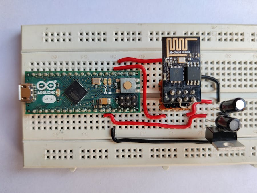
After the connections, your build should look something like this :
/* Project Name : Using ESP-01 module with Arduino Micro
 * For : Arduino Micro/Leonardo/Due/Pro Micro (ATMega 32U4) & ESP8266 01 WiFi Module with Ai-Thinker Firmware
 * Author : Advik Singhania
 * Created On : 30th October, 2020; 04:24 AM IST
*/

void setup() {
  Serial1.begin(115200); // ESP-01 module operates at 115200 baud rate
  Serial.begin(9600);    // while the Serial Monitor uses 9600 baud rate
}

void loop() {
  while(Serial1.available()>0) // While the data output is available on the Serial1 interface(the ESP-01 module)
    Serial.write(Serial1.read());//Write it into the Serial Monitor
  while(Serial.available()>0) // while the data is available input is available in the Serial Interface
    Serial1.write(Serial.read());//Send it to the ESP-01 Module
}
We initialize the baud rates for the ESP module and the Serial Monitor in the setup() function. And add two different single-line loops to read and print the data from one interface to another. This is as simple as it can get.
Now, you need to select the right Board and Port from the Tools section and upload it to your board (remove the RX, TX connections before doing so).
Upon successul compilation and upload, connect the wires again and open the Serial Monitor. Now, we need to type some AT commands to see if it's working properly.
AT: The output should look like this
AT
OK
AT+RST: This resets the board and prints a lot of garbage before saying:
ready
AT+GMR: Prints the version info of the board and the firmware installed
If these commands are working successfully, then pat yourself on the back. You have successfully completed this tutorial. goto: Step Five
If not, try troublleshooting the problems. Make sure the baud rate of serial monitor is set it 9600 baud; close and reopen the serial monitor; hard reset the board by connecting the RST pin to the GND for a while; check your connections; try installing the firmware again. And if everything fails, feel free to comment below and ask your doubts.
Step Five: Done. What's Next?Now you should try to learn a few AT commands, available in the documentation link provided above. Try making some projects on your own and share them in the comments.


_PnKPri8a6q.jpg?auto=compress%2Cformat&w=48&h=48&fit=fill&bg=ffffff)


Comments
Please log in or sign up to comment.