


Hardware components | ||||||
_ztBMuBhMHo.jpg?auto=compress%2Cformat&w=48&h=48&fit=fill&bg=ffffff) |
| × | 1 | |||
 |
| × | 1 | |||
 |
| × | 1 | |||
The only difference between Ultrasonic Sensor and Radio Altimeter is that former uses "Sound waves" and latter uses "Light waves" and hence the difference between their speed of propagation in atmosphere.
IntroductionThe Barometric Altimeter provides altitude with respect to fixed datum that is AMSL – Above Mean Sea Level altitude. The IMU – Inertial Measurement Units like MEMS – Micro Electro Mechanical Systems can only provide the information of attitude of aircraft relative to its axis. So there is a need for third sensor to measure height of aircraft above ground and relative vertical movement between aircraft and ground (terrain). Such system exists in modern airplanes as GPWS – Ground Proximity Warning System, which employs RAM – RADAR Altimeter to measure the AGL-Above Ground Level height. Since the compact sized programmable RAM is not available to be used with R.C. System, we should have to rely on other means to measure the distance. That way is to use the Ultrasonic Distance Measuring Unit, which is widely available and reliable in its operating range.
ImportanceThe falling of the aircraft can be measured by IMUs like MPU-6050, MPU-9250 and so many. But what if aircraft is in level flight at constant altitude and the ground is coming closer to the aircraft due to slope or there is a sudden step in ground like a stone or anything else, it can lead to a catastrophe. Such incidents are known as CFIT - Controlled Flight Into Terrain in Aeronautical studies. Measuring the obstacles beneath the aircraft is importance of this project. All you need to do is just attach this system on aircraft and place the Ultrasonic sensor under the aircraft facing downwards towards land.
The theory of operation of echo location is simple :
- The Transmitter sends a pulse of Ultrasonic sound of some time interval.
- This pulse travels through the air and if there is some obstruction, than it reflects from obstruction.
- The Receiver receives this reflected pulse and the measures the time delay between transmission and receiving of pulse.
- Since, the propagation of sound wave can be fairly considered as straight, the sound wave covers twice the distance between the transmitter and the obstruction during this time period.
- So, the distance can be found using the simple formula of speed as follows :
Note that the code is fully compatible with Arduino MEGA without any modification and so same pin numbers as of UNO.Measurement Principles
Principle of Distance Measurement :
- Using Echo - Location
Principle of Sensing :
- The Brightness of LED is negatively proportional to the height.
- The Rate of Blink is Proportional to Rate of Descent
So, the brightness of LED increases if the aircraft gets closer to the ground at lower height and decreases if aircraft gets away from ground at moderate height. Also the "Blinking Frequency" will increase if aircraft is falling and decrease if aircraft is climbing.
Note that we have considered the range of 0 to 1 meter above ground for achieving above noted goals in following codes. However, you can extend your range up to the reliable operating range of your Ultrasonic distance measurement sensor which is generally up to 4 meters.
Actual setupint triggerpin=10;
int echopin=11;
long duration;
long distance;
long x;
void setup() {
// put your setup code here, to run once:
pinMode(triggerpin,OUTPUT);
pinMode(echopin,INPUT);
pinMode(9,OUTPUT);
Serial.begin(9600);
}
void loop() {
// put your main code here, to run repeatedly:
digitalWrite(triggerpin,LOW);
delayMicroseconds(2);
digitalWrite(triggerpin,HIGH);
delayMicroseconds(10);
digitalWrite(triggerpin,HIGH);
duration=pulseIn(echopin,HIGH);
x=(duration/2)/29.1; //1/29.1=0.034 ~ speed of sound converted into centimeters per microsecond
Serial.print("Distance :");
Serial.print(x);
x=map(x,0,100,255,0); //mapping the intensity as per distance
Serial.print("\t");
Serial.print(x);
Serial.println();
if(x<255 && x>10) //code stability condition
{
analogWrite(9,x);
}
else if (x<10)
{
analogWrite(9,0);
}
else
{
analogWrite(9,0);
}
}
 int triggerpin=10;
int echopin=11;
long duration;
long distance;
long x;
long x1=45;
int z;
void setup() {
 // put your setup code here, to run once:
pinMode(triggerpin,OUTPUT);
pinMode(echopin,INPUT);
pinMode(9,OUTPUT);
Serial.begin(9600);
}
void loop() {
 // put your main code here, to run repeatedly:
digitalWrite(triggerpin,LOW);
delayMicroseconds(2);
digitalWrite(triggerpin,HIGH);
delayMicroseconds(10);
digitalWrite(triggerpin,HIGH);
duration=pulseIn(echopin,HIGH);
x=(duration/2)/29.1;
Serial.print("Distance :");
Serial.println(x);
z=(x1-x)/2;
x1=x;
Serial.print("\t z :");
Serial.println(z);
z=map(z,-10,6,1000,5);
analogWrite(9,HIGH);
delay(z);
analogWrite(9,LOW);
delay(z);
}
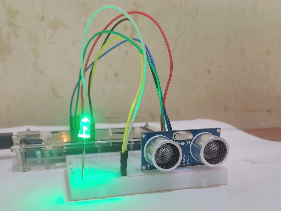
In above sketches, the pin 9 is attached LED.
Note that above code for rate of change of height is very fine tuned to measure very slight descent of aircraft downwards, you can change the sensitivity by changing the values in map function in above code, but proceed with keeping reality of flight in mind, where it is most essential to measure even the slight descent of aircraft which may result in free fall further and then crash.
Videos :The setup shown in videos is for testing purpose only, it is not mounted under an aircraft !!
Applications- For Night Flying, can be used with array of lights and may be buzzer as warning signal.
- The data can be used to produce the terrain map, so called terrain mapping.
- As Autopilot input to avoid collision with ground and to maintain constant AGL altitude, like to Elevator up to perform pitch up if flying closer to ground.
- For Aerial Delivery systems to be used by E-Commerce companies.
- The Cone of propagation of Ultrasonic Transmitter is very narrow of order of 12° (as per our experimental measurements suggest). Meaning The Distance measurement becomes unreliable for AOA (Angle of Attack ) more than 12° or for terrain having slope larger than 12°. This limitation can be over come by pivoting the sensor on Gimbal and rotating the sensor with Servo Motor or using multiple Ultrasonic Sensors at different angles and Synchronization between these sensors.
- The speed of Sound is a function of Temperature of ambient air and Moisture Content in air, however this limitation can be overcome by calibrating the Code with local Atmospheric conditions using any Temperature Sensor available as speed of Sound is given by :
- So, we need to add extra code for calibration for speed of sound or just change the speed of in above code according to the temperature in which aircraft is intended to operate.


Comments
Please log in or sign up to comment.