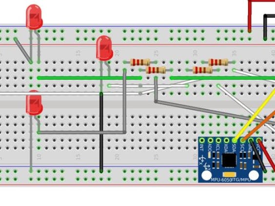
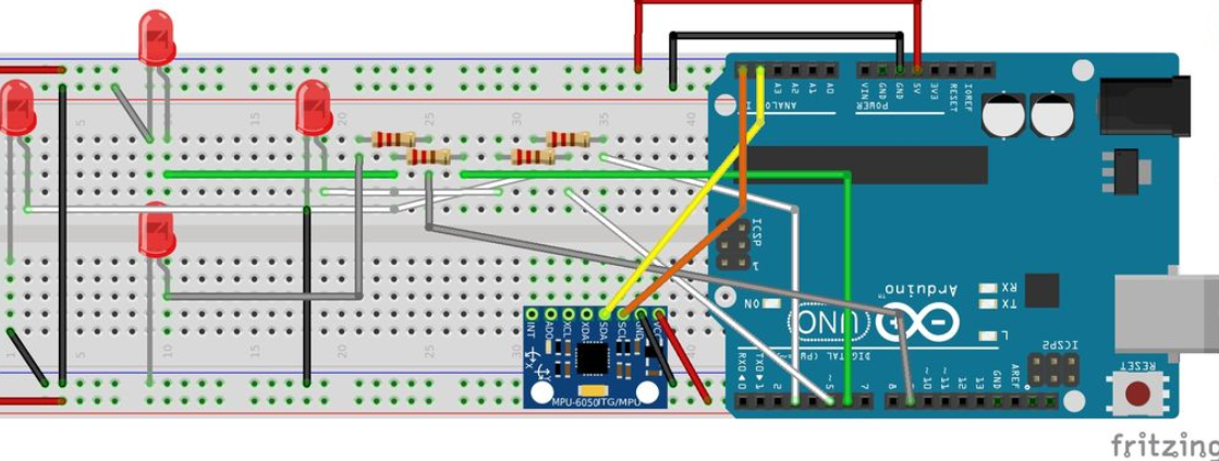
#define SIMPLE_IMPLEMENTATION false

const int frontLed = 3;
const int bottomLed = 5;
const int rightLed = 6;
const int leftLed = 9;
long int lastPrintTime;

typedef struct
{
byte pin;
byte positionInsideGroup;
char thePosition; // Left, Right, Up, Down
byte minAngle;
byte maxAngle;
} ledConfig;

ledConfig leds[] = {
{3, 1, ‘u’, 31, 45},
{12, 2, ‘u’, 16, 30},
{11, 3, ‘u’, 5, 15},
{5, 1, ‘d’, 5, 15},
{6, 2, ‘d’, 16, 30},
{7, 3, ‘d’, 31, 45},
{8 , 1, ‘r’, 5, 23},
{9, 2, ‘r’, 24, 45},
{10, 1, ‘l’, 5, 23},
{4, 2, ‘l’, 24, 45},
};

#include “I2Cdev.h”
#include “MPU6050_6Axis_MotionApps20.h”
#if I2CDEV_IMPLEMENTATION == I2CDEV_ARDUINO_WIRE
#include “Wire.h”
#endif

MPU6050 mpu;

bool dmpReady = false; // set true if DMP init was successful
uint8_t mpuIntStatus; // holds actual interrupt status byte from MPU
uint8_t devStatus; // return status after each device operation (0 = success, !0 = error)
uint16_t packetSize; // expected DMP packet size (default is 42 bytes)
uint16_t fifoCount; // count of all bytes currently in FIFO
uint8_t fifoBuffer[64]; // FIFO storage buffer

// orientation/motion vars
Quaternion q; // [w, x, y, z] quaternion container
VectorInt16 aa; // [x, y, z] accel sensor measurements
VectorInt16 aaReal; // [x, y, z] gravity-free accel sensor measurements
VectorInt16 aaWorld; // [x, y, z] world-frame accel sensor measurements
VectorFloat gravity; // [x, y, z] gravity vector
float euler[3]; // [psi, theta, phi] Euler angle container
float ypr[3]; // [yaw, pitch, roll] yaw/pitch/roll container and gravity vector
volatile bool mpuInterrupt = false; // indicates whether MPU interrupt pin has gone high

void setup()
{
#if I2CDEV_IMPLEMENTATION == I2CDEV_ARDUINO_WIRE
Wire.begin();
TWBR = 24; // 400kHz I2C clock (200kHz if CPU is 8MHz)
#elif I2CDEV_IMPLEMENTATION == I2CDEV_BUILTIN_FASTWIRE
Fastwire::setup(400, true);
#endif

Serial.begin(9600);
while (!Serial); // wait for Leonardo enumeration, others continue immediately
Serial.println(F(“Initializing I2C devices…”));
mpu.initialize();
Serial.println(F(“Testing device connections…”));
Serial.println(mpu.testConnection() ? F(“MPU6050 connection successful”) : F(“MPU6050 connection failed”));
Serial.println(F(“Initializing DMP…”));
devStatus = mpu.dmpInitialize();
mpu.setXGyroOffset(220);
mpu.setYGyroOffset(76);
mpu.setZGyroOffset(-85);
mpu.setZAccelOffset(1788); // 1688 factory default for my test chip
if (devStatus == 0) {
// turn on the DMP, now that it’s ready
Serial.println(F(“Enabling DMP…”));
mpu.setDMPEnabled(true);
Serial.println(F(“Enabling interrupt detection (Arduino external interrupt 0)…”));
attachInterrupt(0, dmpDataReady, RISING);
mpuIntStatus = mpu.getIntStatus();
Serial.println(F(“DMP ready! Waiting for first interrupt…”));
dmpReady = true;
packetSize = mpu.dmpGetFIFOPacketSize();
} else {
Serial.print(F(“DMP Initialization failed (code “));
Serial.print(devStatus);
Serial.println(F(“)”));
}
if (SIMPLE_IMPLEMENTATION) {
initializeLEDsSimple();
} else {
initializeLEDsMultiple();
}
lastPrintTime = millis();
}

void loop()
{
if (!dmpReady) return;
mpuInterrupt = false;
mpuIntStatus = mpu.getIntStatus();
fifoCount = mpu.getFIFOCount();
if ((mpuIntStatus & 0x10) || fifoCount == 1024) {
mpu.resetFIFO();
Serial.println(F(“FIFO overflow!”));
} else if (mpuIntStatus & 0x02) {
while (fifoCount < packetSize) {
fifoCount = mpu.getFIFOCount();
}
mpu.getFIFOBytes(fifoBuffer, packetSize);
fifoCount -= packetSize;
mpu.dmpGetQuaternion(&q, fifoBuffer);
mpu.dmpGetGravity(&gravity, &q);
mpu.dmpGetYawPitchRoll(ypr, &q, &gravity);
int x = ypr[0] * 180/M_PI;
int y = ypr[1] * 180/M_PI;
int z = ypr[2] * 180/M_PI;
Serial.print(y);Serial.print(“\t”);Serial.println(z);
if (SIMPLE_IMPLEMENTATION) {
flashLEDsSimple(x, y, z);
} else {
flashLEDsMultiple(x, y, z);
}
}
}

void initializeLEDsSimple()
{
pinMode(frontLed, OUTPUT);
pinMode(bottomLed, OUTPUT);
pinMode(rightLed, OUTPUT);
pinMode(leftLed, OUTPUT);
}

void initializeLEDsMultiple()
{
for (int i=0; i<10; i++) {
Serial.println(leds[i].pin);
pinMode(leds[i].pin, OUTPUT);
}
delay(3000);
}

void flashLEDsSimple(int x, int y, int z)
{
if (y > 0) {
analogWrite(rightLed, y*4);
analogWrite(leftLed, 0);
} else {
analogWrite(leftLed, y*4*-1);
analogWrite(rightLed, 0);
}
if (z > 0) {
analogWrite(bottomLed, z*4);
analogWrite(frontLed, 0);
} else {
analogWrite(frontLed, z*4*-1);
analogWrite(bottomLed, 0);
}
}

void flashLEDsMultiple(int x, int y, int z)
{
for (int i=0; i<10; i++) {
//Serial.print(z);Serial.print(“,”);Serial.print(leds[i].thePosition);Serial.print(“,”);Serial.println(leds[i].minAngle);
bool modified = false;
if (z < 0 && leds[i].thePosition == ‘u’ && abs(z) > leds[i].minAngle) {
digitalWrite(leds[i].pin, HIGH);
modified = true;
}
if (z > 0 && leds[i].thePosition == ‘d’ && abs(z) > leds[i].minAngle) {
digitalWrite(leds[i].pin, HIGH);
modified = true;
}
if (y < 0 && leds[i].thePosition == ‘l’ && abs(y) > leds[i].minAngle) {
digitalWrite(leds[i].pin, HIGH);
modified = true;
}
if (y > 0 && leds[i].thePosition == ‘r’ && abs(y) > leds[i].minAngle) {
digitalWrite(leds[i].pin, HIGH);
modified = true;
}
if (!modified) {
digitalWrite(leds[i].pin, LOW);
}
}
}

void dmpDataReady()
{
mpuInterrupt = true;
}


_3u05Tpwasz.png?auto=compress%2Cformat&w=40&h=40&fit=fillmax&bg=fff&dpr=2)

Comments
Please log in or sign up to comment.