Hey whats up Guys! Akarsh here from CETech.
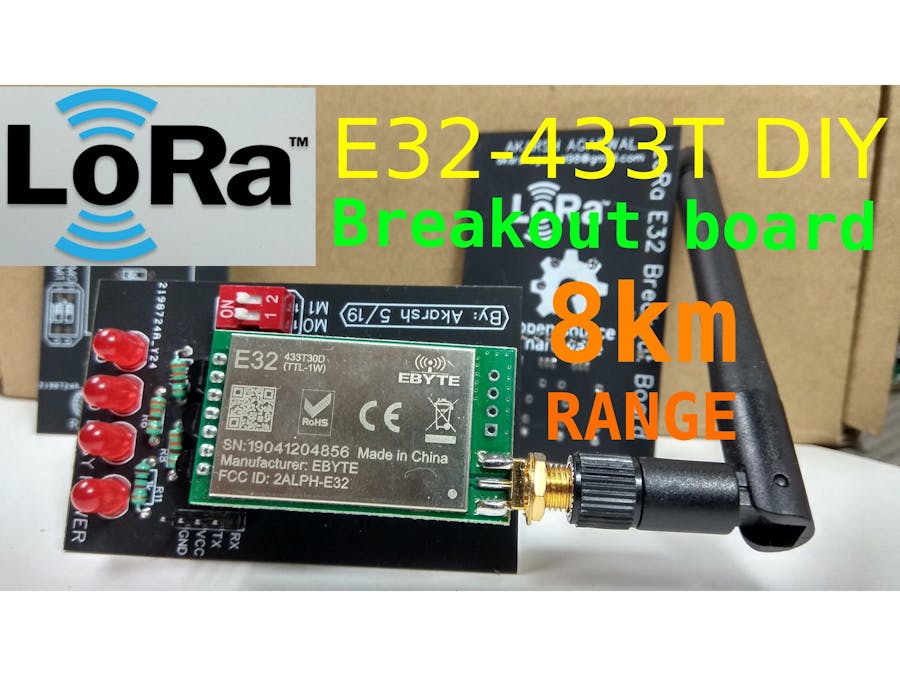
This project of mine is more of a learning curve to understand the working of the E32 LoRa module from eByte which is a high power 1 watt transceiver module.
Once we understand the working, I have designed a PCB which is a breakout for this E32 module which exposes the UART bus for directly talking to the E32 module without any external circuits.
Lastly we will test our module by setting up a link between 2 modules and send/receive data using this LoRa link
Lets start with the fun now
PartsYou can find the LoRa modules from eByte on the following links from LCSC:
E32 1W module: https://bit.ly/2R4xxct
E32 100mW module: https://bit.ly/2ZjbLo6
Antenna 433MHz: https://bit.ly/2WBUk5A
Get PCBs for Your Project ManufacturedYou must check out PCBGOGO for ordering PCBs online for cheap!
You get 10 good quality PCBs manufactured and shipped to your doorstep for 5$ and some shipping. You will also get a discount on shipping on your first order.
PCBGOGO has the capability of PCB assembly and stencil manufacture as well as keeping good quality standards.
Do check them out If you need to get PCBs manufactured or assembled.
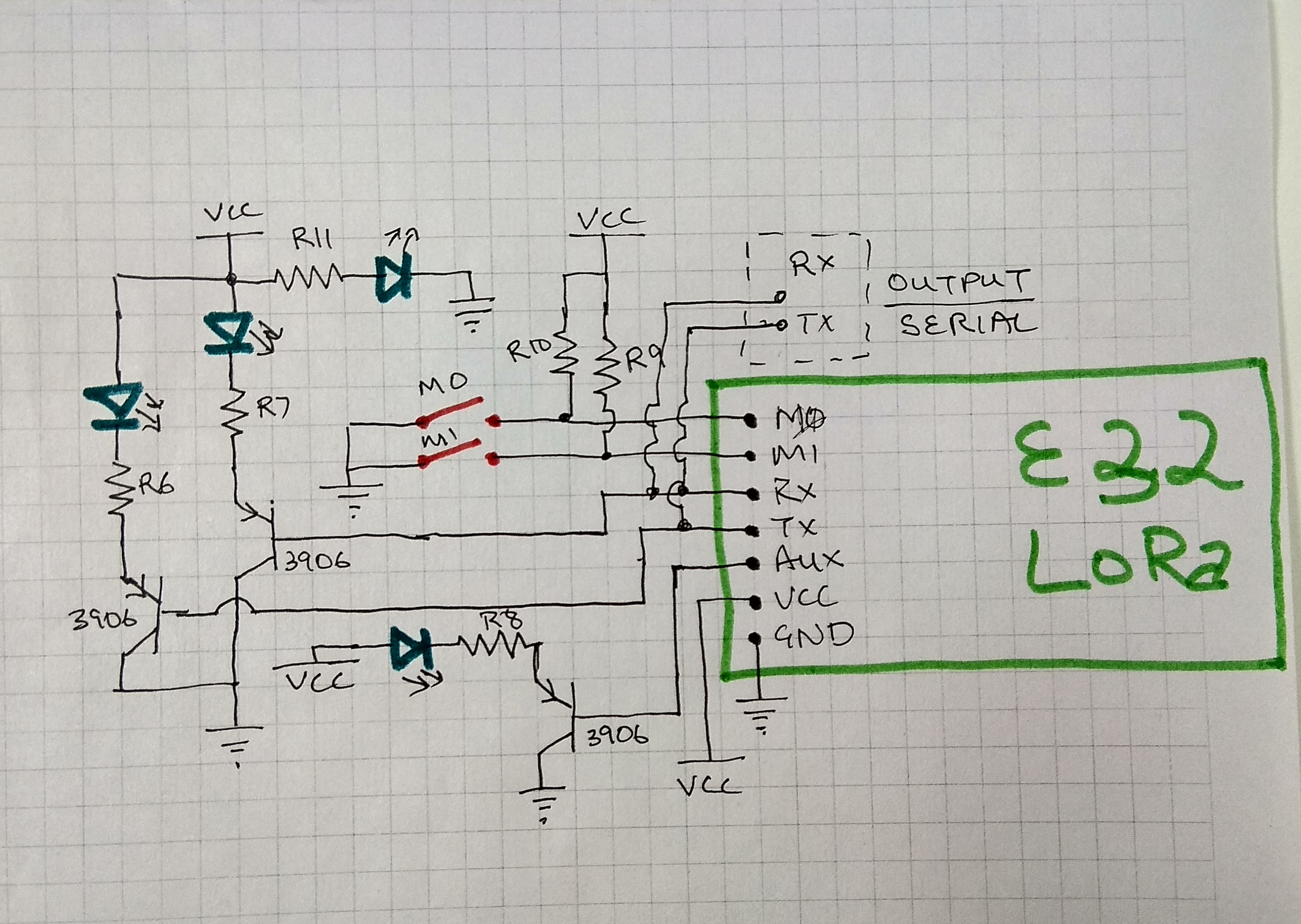
The most important connection to be made is of the M1 and M0 pins. They need to be connected to either GND or VCC for the operation of the module and cannot be left floating. We will learn more about the different mode selection using M1 and M0 in the next step.
AUX pin is an output pin which shows the busy status of the module so we attach a LED to this pin using a 3906 transistor to know the status of the E32.
Lastly I have also attached a couple of LEDs on the Rx and Tx pins so that when data transmission is happening over UART its visible on the LEDs.
Changing the voltage of the pins M1 and M0 different modes of the module can be set.
We can see the different modes on the above table.
I mostly focus on the Mode 0 and Mode 3. For normal LoRa use I keep the module on Mode 0 and for configuration I keep it on Mode 3.
Breakout BoardI designed a PCB using the above circuit diagram and got it manufactured.
The PCB exposes the UART port directly and the E32 can be used without any external circuitry with any microcontroler directly.
So I soldered the components on the PCB and tested the LoRa link in the next step.
I connected one module using an FTDI module to a PC and set the mode switch of M0 and M1 to 1 and 1 for parameter setting.
After doing that I opened the RF Setting software and after selecting the correct COM port, hit the GetParam button which fills up all the boxes in the software and confirms that the module is working.
Then in second setup, I switched the mode to Mode 0 by doing M1 & M0 to 0 & 0. I did this for 2 boards and connected both of them to power supply. Then started sending data to one module over UART and I started observing the TX pin on the other module flashing which confirmed the setup of the wireless LoRa link. Watch my video for the same demo.


_3u05Tpwasz.png?auto=compress%2Cformat&w=40&h=40&fit=fillmax&bg=fff&dpr=2)
Comments
Please log in or sign up to comment.