In this article discuss about control a servo motor with a potentiometer. My previous is discussing about installation of Arduino IDE interface a Servo motor with Arduino Uno. you can read that article here. If you never read that article or don't know how to interface a servo motor with Arduino, please read that article. Because here we are can't go forward without basics. You can't build a great building on a week foundation.
How it works?
First we read the potentiometer reading using analogRead() function. By rotate the knob or slide the botton of potentiometer, will change the voltage to the Arduino analog pin. The voltage range is 0-5V. The ADC in the Arduino will convert analog signal to digital signal. In default, 0V will output as 0 in digital and 5V will output as 1023. But in this project we only want from 0 to 180. For this we use the map() function. This function returns the desired range and we write that value to servo.
This article is talking about,
- Interfacing potentiometer.
- Use of map() function.
- Use of analogRead() function
Before starting we need to understand what is potentiometer. If you already know kindly please skip this part.
PotentiometerThis is a electronic component which act as a adjustable voltage divider. Actually it's a type of resistor. which can change the resistance by rotating a knob or a slider. It have a wide verity of use. ie. Volume Control of Music equipment, joystick, etc..
It's time to start.
Buy electronic components with free shipping on utsource.net
Step - 1
Open Arduino IDE and add the header named Servo.h. Then declare a variable to call the Servo motor. Here I am using the same as the previous article. So the satement is looks like "Servo Myservo". Then we need to declare another integer variable to control the servo position. Actually we use this integer to store the mapped value. I named it as "pos". But you use put any name to your variable.
#include<Servo.h>
Servo Myservo;
int pos;
Step - 2
In the void setup() function, first we need to set the Arduino Pin A0 as input. For this we can use the function "pinMode". The syntax is "pinMode(pin, mode)". The pin here we use are A0 and mode is "INPUT".
pinMode(A0,INPUT);Now we need to set the control pin for Servo motor. Here we using the Arduino Digital pin 3 for this purpose. For more click here.
Myservo.attach(3);void setup() part is completed. Now the void loop() part.
Step - 3
In the void loop() function first we use the "map()" function to map the value. This function is used for re-map the value from one range to another range. The syntax is "map(value, fromLow, fromHigh, toLow, toHigh)". This function returns the mapped value. The parameters used in this function are described below,
- value -Simply value is the number to map. Actually this is source value. The value from potentiometer and it convert by the help of Analog to Digital Converter(ADC). The ADC output a value, and we read that value by using analogRead() function. Here we using the A0 pin of Arduino Uno. So, the parameter "value" is "analogRead(A0).
- fromLow - The lower bound of value's voltage range. Here it is 0. Because the ADC output the 0 is corresponding to the Voltage 0.
- fromHigh - The upper bound of value's voltage range. Here it is 1023. Because the ADC output the 1023 is corresponding to the Voltage 5.
- toLow - The lower bound of the value's target range. It is 0. Because we need the minimum value is 0.
- toHigh - The upper bound of the value's target range. It is 180. Because our desired maximum value is 180.
We store this value to the variable "pos"
So it is look like,
pos=map(analogRead(A0),0,1023,0,180);Step - 4
Next we need to write the value in the variable "pos" to Servo.
Myservo.write(pos);The coding part is completed.
Upload the code to arduino.
The complete code is given in the Code Section.
Step - 5
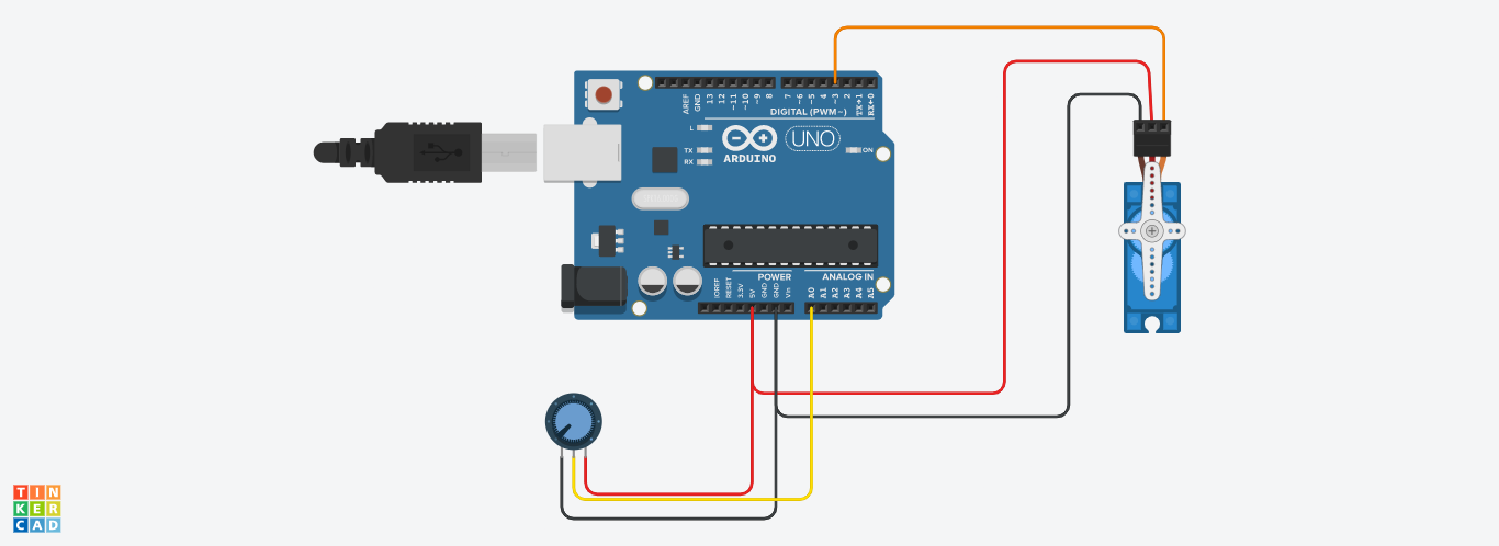
Now need to wire the circuit. Basically this is a simple circuit. Here we using the Male to Male breadboard jumber wire.
We required 3 jumber wire. First cut and stripe the one end of each three wires. And solder it to the three terminals of potentiometer. Then connect the jumber wires to the Arduino. Refer the circuit diagram with this article.
You can see the simulation of this project here.
Please on't copy-paste my code. Understand the each lines and make your own.
You can join our telegram group : t.me/INNOVATIONNN Or search INNOVATION. Any doubts, you can ask there.
Please share your feedback in comments section.


_ztBMuBhMHo.jpg?auto=compress%2Cformat&w=48&h=48&fit=fill&bg=ffffff)


Comments
Please log in or sign up to comment.