Bluetooth is a one of the great example for wireless connectivity. It is used in many fields. Bluetooth consumes very small amount of energy. Do you know about Smartphone controlled robot or car. Commonly one of these two wireless technology is used in Smartphone controlled robot. One is WIFI and other is Bluetooth. And another commonly used wireless technology for controlling Robot car is RF. Which is the same remote and receiver used in drones. Here we are going to interface a Bluetooth Module (HC-05) with Arduino Uno. And describe each line of code. Then we control the builtin LED of Arduino Uno from smartphone via Bluetooth.
Before starting we must know about the HC-05
HC-05 Bluetooth ModuleHC-05 is a Bluetooth module which can communicate in two way. Which means, It is full-duplex. We can use it with most micro controllers. Because it operates Serial Port Protocol (SSP). The module communicate with the help of USART (Universal Synchronous/Asynchronous Receiver/Transmitter ) at the baud rate of 9600. and it also support other baud rate. So we can interface this module with any microcontroller which supports USART. The HC-05 can operate in two modes. One is Data mode and other is AT command mode. When the enable pin is "LOW" the HC-05 is in Data Mode. If that pin set as "HIGH" the module is in AT command mode. Here we operate this module in Data Mode.
Technical Specifications
- Operating Voltage: 4V to 6V (Typically +5V)
- Operating Current: 30mA
- Range: <100m
- Works with Serial communication (USART) and TTL compatible
- Can be easily interfaced with Laptop or Mobile phones with Bluetooth
You can see the more about the module in the datasheet.
it's time to start.
Step - 1
First I am going to create a sketch for Arduino Uno to Interface the HC-05
Open Arduino IDE.
Here we make this project without any library. First declare a variable named "inputByte" as char datatype. Alternatively you can use any variable name. Here we use the character to control the LED. And set the initial value of "inputByte" is "z" (it is lowercase). Why it is "z" ? See the String table. It is used to set the initial state of LED as "LOW" ( When turn on the Arduino, Set the LED is off).
char inputByte='z';Step - 2
Next we need to code the setup part. HC-05 use the serial communication. So begin the serial communication by using the function "Serial.begin()". Set the baud rate as 9600. Then set the digital pin 13 as a "OUTPUT" pin. Because this is the pin which internally connected to the inbuilt LED.
void setup(){
Serial.begin(9600);
pinMode(13,OUTPUT);
}
Setup part is completed.
Step - 3
Next I am going to code the loop part. Use a while loop and the function "Serial.available()". This function returns the number of bytes available to read. The body part of while loop works only the "Serial.available()" is greater than 0. Then read the data available in serial port. For that, I use the function "Serial.read()". Then store it to "inputByte". Then use an "if" condition. Make the pin 13 "HIGH" if the "inputByte" is "Z" (upper case).Because the the App will send "z" when the button is in ON mode. This is for turn on the LED. Next I use a "else if" condition to turn off the LED. condition for turn off the LED is "inputByte==z"(lower case). Because the the App will send "Z" when the button is in OFF mode. For more see the String table.
void loop() {
while(Serial.available()>0){
  inputByte= Serial.read();
  Serial.println(c);
  if (inputByte=='Z'){
  digitalWrite(13,HIGH);
  }
  else if (inputByte=='z'){
  digitalWrite(13,LOW);
  }
  }
}
The loop part is completed. You can see the complete code in the code section of this article. Then upload the code to Arduino Uno
Please make sure the Rx and Tx pin of HC-05 remove from Arduino Uno while uploading. Otherwise you may encounter with some problem to upload the code.
Step - 4
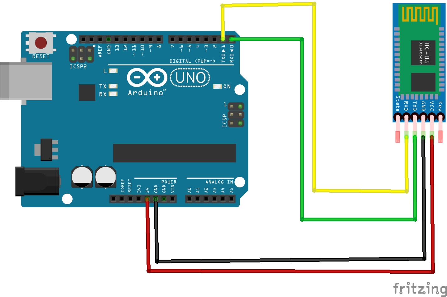
Connections
Arduino Uno HC-05
Rx - Tx
Tx - Rx
5v - +5v
GND - GND
Connection is completed. After turn on the Arduino Uno, The indicator LED in the HC-05 will start blinking continuously
App configuration.
Now we need install an App in Smartphone. You can download the app here. After installation Open the app then you can see the string table. Which shows the character corresponding to each button. Click "next" and then click "Finish". Then you can see a scan button. Click that and pair the HC-05 with your phone. You can use the key "1234". After pairing back to App and turn on "Switch 1".
After paring the indicator LED in the HC-05 will stop continuous blinking and blink the same LED with some delay.
"Z" is represent the ON state of Switch 1 and "z" is represent the OFF state of Switch 1. You can see more in String Table.
You can use any application, careful about the string send to HC- 05 and string in the condition statement. The android application used here is not developed by me. I respect the corresponding developer. You can make your own Android app by using MIT App inventor. I strongly recommend for that.
Please don't copy-paste my code. Understand the code and make your own
You can join our telegram group here or search INNOVATION.
STAY HOME, STAY SAFE, STAY CREATIVE. Let break the chain.
Follow me on,
Instagram : five_volt_player
Facebook : Akshay Joseph
Github : akshayjoseph666
Contact : akshayjoseph666@gmail.com
Share your experience and suggestions on the comment box.
Previous articles Automatic Water Tap, Automatic Hand Sanitizer, Interface Ultrasonic sensor with Arduino Uno, Control Servo motor with Arduino Uno and Pushbutton, Control Servo motor with Arduino Uno and POT, Servo Motor Interface with Arduino Uno, IR Controlled Home Appliances With Saving Previous State, Touchless Hand Wash Timer


_ztBMuBhMHo.jpg?auto=compress%2Cformat&w=48&h=48&fit=fill&bg=ffffff)


Comments