


Hardware components | ||||||
 |
| × | 1 | |||
| × | 1 | ||||
| × | 1 | ||||
| × | 1 | ||||
Software apps and online services | ||||||
| ||||||
Hand tools and fabrication machines | ||||||
 |
| |||||
DISCLAIMER: Working with high voltage A/C can be deadly and dangerous. It can also create a fire hazard if not done correctly. Do not attempt to replicate this project unless you are a certified electrician. If you continue reading and attempt this, you are doing so at your own risk.
What is this?This project will show you how to create your own WiFi light switch and be able to control your light from a native mobile app, IFTTT, or any webhook. The buttons can can be programmed with 6 different modes.
When leaving my house, I would often forget to turn the lights off. This has been a recurring problem so I searched for a solution. I couldn't find a nice looking 3 gang light switch that would be affordable, connected to the cloud and easily controllable natively from my phone.
Enter WiFi My Lights
WiFi My Lights started as a WiFi Project. However, when I discovered the possibilities with 6 different modes for each button, I started playing around with custom settings such as ALL LIGHTS OFF with a long press! Below I will outline the steps I took so you can also make one!
Instructions - ElectricalStep 1: First thing I did was purchased the Relay Shield and the Particle Photon from Particle.io
Step 2: Turn off the 110V circuit in from your circuit breaker panel. If you are unsure about this, consult with an electrician.
Step 3: The fun part begins: unscrew the wall plate cover that you'd like to replace.
Step 4: Flip a switch to ensure there is no electricity there. Success will look like nothing happened. i.e.: no lights turn on. If lights do come on, go back to Step 2.
Step 5: Doing one switch at a time, disconnect both ends of the copper wire that terminate on the original switch and insert them into the Particle Relay Shield terminals. See picture below:
Step 6: After you are done with all three relays, it should roughly look like this:
Step 7: Program your Photon using the code below called 'wifi-lights.ino'
Step 8: Download the Blynk App on your phone. It will give you a token which you'll need to replace in this section of the code:
// You should get Auth Token in the Blynk App.
// Go to the Project Settings (nut icon).
char auth[] = "the token from Blynk goes here - keep the quotation marks";
Step 9: Drag and Drop Components from the Blynk library of 'Parts' until it looks like the screenshots below. Make sure you assign Virtual Pins in the Blynk app according to the following key:
Virtual Pin V1 => Push Button 1
Virtual Pin V2 => Push Button 2
Virtual Pin V3 => Push Button 3
Virtual Pin V7 => Push Button 4
Virtual Pin V4 => Blynk LED1
Virtual Pin V5 => Blynk LED2
Virtual Pin V6 => Blynk LED3
Step 10: Do a visual inspection of all thick copper wires and make sure they are not touching. Go back to your circuit breaker panel and turn on the circuit you are working on. Test your app with the Relay Shield unattached. Your lights should turn on and off!
Step 11: Turn off circuit breaker.
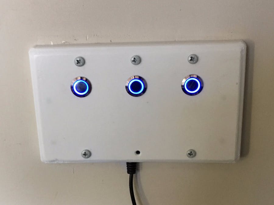
Instructions - Mechanical AssemblyStep 12: 3D Print the file attached called 'WiFi Lights.stl'. I printed it in white so it looks like a wall plate mount.
Step 13: Connect the pushbuttons as specified in the schematic below. Although not shown, I also connected the LED lights on the pushbutton to 5V so they are illuminated all the time.
Step 14: Insert 3mm heat set inserts into the 3D printed wall mounted plate using an old soldering iron. Attach the Relay Shield to the the 3D printed wall mounted plate.
Step 15: Attach plate to wall using long screws and you are done!


Comments
Please log in or sign up to comment.