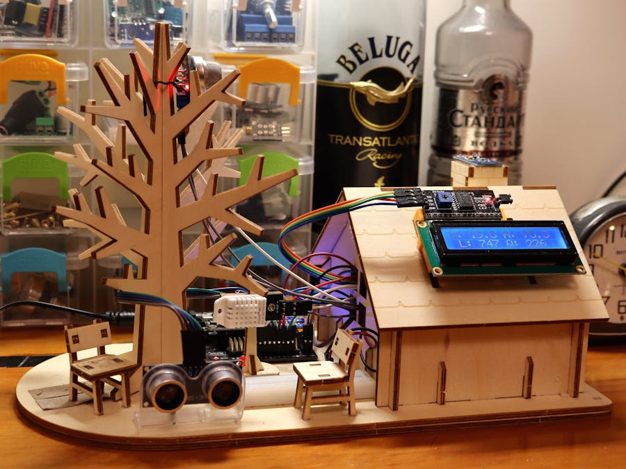
This is an old project of mine; about a year ago I made this "smart home" (or home automation) based on BBC micro:bit as a practice project. Earlier this year I remade it into a ESP8266/MicroPython version. The wiring may look complicated, but the central idea is pretty straightforward.
The goal of making a smart home project, of course, is to learn to control various sensors and do things under specific conditions, maybe with different priority or delay time.
- Board: NodeMCU V3 (ESP8266 ESP-12E) with a breakout board
- Power: 7.5V 1A to the breakout board (which in turn provides 5V and 3.3V power)
- LCD 16x2 display (I2C) (the address maybe 0x27 or 0x3F; power needed may be 3.3V or 5V)
- BH1750FVI (GY-30 or GY-302) light sensor (I2C) (3.3V)
- MPU-6050 3-axis accelerometer/gyroscope (I2C) (3.3V)
- DHT22 temperature/humidity sensor (5V)
- HC-SR04P ultrasonic sensor (3.3V) (the non-P versions work too but require 5V power)
- MQ2 gas sensor (5V)
- Active piezo buzzer (which can be triggered with LOW voltage) (3.3V)
- A red LED
- Relay module (5V)
Most of the ESP8266 boards are almost the same in functionality. Be noted that NodeMCU V3 (CH340 USB chip) is wider than V2 (CP2102 USB ), both have their own breakout board.
Due to some reason, the DHT22 won't respond unless you power it up after the NodeMCU is on. Hence I used a relay as the power switch for DHT22.
Also, MQ2's analog signal is 5V-based, and the board's A0 pin is 3.3V only. So I use resistors to build a voltage divider circuit.
Software- NodeMCU V3's CH340G USB chip driver: http://www.wch-ic.com/downloads/CH341SER_EXE.html
- MicroPython firmware: v1.12 https://micropython.org/download (you can use PyFlasher to flash the firmware)
- My editor of choice is Thonny.
- LCD 16x2 library: https://github.com/dhylands/python_lcd
- MPU-6050 library: https://github.com/adamjezek98/MPU6050-ESP8266-MicroPython
- BH1750 library: https://github.com/catdog2/mpy_bh1750fvi_esp8266
- HC-SR04 library: https://github.com/rsc1975/micropython-hcsr04
The MicroPython firmware has included a DHT22 driver.
Upload .py library files onto the board. See How to upload.py-files onto an ESP8266 running MicroPython or use Thonny's File/Save copy option.
FunctionsThe board connects to your WiFi router on start. If the connection is lost afterward, the board will reboot itself.
The LCD displays light level (illuminance in Lux), temperature (celsius), humidity (%) and MQ2's analog reading, which updated for every 2 seconds.
The LCD's backlight switches on when you are in front of the house (detected by the ultrasonic sensor).
The board transmits temperature, humidity and MQ2 reading via IFTTT's Webhook API to a Google spreadsheet in my Google Drive for every 10 seconds. (The service allows you to send 3 data at the same time.) The API would log the time as well.
The buzzer would be triggered if the house is tilted over 3 degrees. Shake the house can achieve the same effect. (Earthquake/burglar alarm.)
The buzzer would also be triggered if MQ2 reading is over 700. (Smoke alarm. Although I have no idea how high the threshold should be.)
There are a lot of videos and articles online teaching you how to use the free IFTTT Webhook service.
The following video was my original micro:bit version: (Some of the sensors and that micro:bit were borrowed from my previous company. After I dumped the PHB-like boss i returned those. I did tried to reuse the motor fan, but it consumed too much power and keep causing problems.)


Comments
Please log in or sign up to comment.