


Hardware components | ||||||
_ztBMuBhMHo.jpg?auto=compress%2Cformat&w=48&h=48&fit=fill&bg=ffffff) |
| × | 1 | |||
| × | 1 | ||||
| × | 1 | ||||
Software apps and online services | ||||||
| ||||||
Before you start reading, we highly recommend that you read the first part of our series, which this article directly follows.
In the second part of the series about automation by SMS, we will show a practical demonstration of Arduino control with the relay module via SMS. You may ask, why are we going to control the relay module? After all, switching a relay is a trivial task - and you're right. With Adeon and the Adeon library, it's really easy and it’s a perfect starting point to explain the important features of the Arduino library. After all, relay switching is a simple but very effective form of automation. And honestly, which one of you ever controlled a relay by SMS?
The example includes the Arduino wiring diagram, module relay and GSM module from SIMCom. However, the Adeon library itself does not depend on a particular GSM module and you can use the hardware of any GSM device manufacturer. However, you have to program the communication between the GSM module and Arduino. With SIMCom modules you don’t need to solve this issue because their support is built directly in the Adeon library, so it’s easier to work with them.
Software for Arduino is also an essential part of the demonstration. The software fragments that we will discuss in this article are part of the Adeon library by default. We will describe the basic functions of the library, which serve both for communication with the GSM module and for receiving SMS messages, as well as for managing users (phone numbers) and user-set parameters.
The full code of this sample can be found here or in the Arduino IDE in File → Examples → Adeon → SIMComGsm.ino
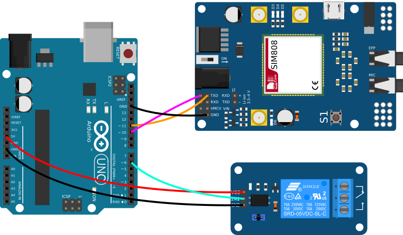
ConnectionThe entire assembly consists of only three components. Arduino Uno will serve as a microcontroller. Next, we will use the already mentioned basic single channel relay module and GSM module.
The GSM module communicates with Arduino via the UART serial interface, whereby the RX pin (GSM) is connected to IC pin 10 (Arduino) and the TX pin (GSM) to IO pin 11 (Arduino). For the GSM module, it is recommended to use an independent power supply (in this case 12 V DC). If GSM is powered independently of Arduino, it is necessary to connect GND Arduino and GSM module.
The relay module is connected to IO pin 6 of Arduino.
Note for the curious: Since Arduino Uno has only one UART serial interface (one serial line), which we use for communicating with a PC, we need to create a second (emulated) serial line to communicate with the GSM module. For that, we use the SoftwareSerial library.
In order for the GSM module to be able to log into the mobile network, we will, of course, need an active SIM card with a recharged credit or flat rate. For the correct functioning of SIMCom modules, we highly recommend removing the PIN code of the SIM card (disable PIN code request).
Importing the library into the Arduino IDEThe Arduino Adeon library is available for download directly in the Arduino IDE (integrated development environment). For advanced users, the library is also available in the PlatformIO development environment. The library is also available for download here.
- Start the Arduino IDE
- Open Library Manager ( Project → Add Library → Manage Libraries )
- Type Adeon in the search box
- Click Install
Note: In order to be able to receive SMS messages in a complete form, it is necessary to adjust the size of the receiving buffer (RX buffer) in the SoftwareSerial.h library, which is a standard part of the Arduino IDE package. The default value is 64 bytes. For our purposes, however, we need the maximum possible capacity, i.e. 256 bytes (the real value of the constant is 255 – indexing starts from zero). The constant is defined in the library header file. The file path is (in Windows OS) by default in:
C:/ProgramFiles(x86)/Arduino/hardware/arduino/avr/libraries/SoftwareSerial/src/SoftwareSerial.hAdjust the value according to the following template:
#define _SS_MAX_RX_BUFF 255 // RX buffer sizeThe following paragraphs describe the code snippets for SIMComGsm.ino. The example is part of the Adeon library and, as the name implies, its implementation supports communication with GSM modules SIMCom.
Features for adding usersTo make the set able to receive SMS messages that we send from the Adeon mobile app, it is necessary to enter our phone number into the program. While entering a phone number into the user list, we can determine its rights. There are three rights in total, namely ADMIN, USER, and HOST. Based on these authorizations, the software determines whether the phone number is authorized to change the values of certain parameters.
void userInit(){
    //add users with ADMIN, USER or HOST rights
    adeon.addUser("420123456789", ADEON_ADMIN);
    adeon.addUser("420987654321", ADEON_HOST);
    adeon.printUsers();
}Now we have two phone numbers. However, in order to be able to change/control the content of an SMS message, we must also enter parameters into the program. Parameters and their values can be used, for example, to determine or change the status of a device that is connected to Arduino. Each parameter must have a unique name that makes it identifiable in the list. The parameter also includes a variable carrying the current value of the parameter (the default value is 0), which may change dynamically depending on the receipt of messages.
There are two functions for adding new parameters. The addParam function (parameter, value) adds a parameter to the list for which no function is linked. In this case, it is not specified what should happen after changing the parameter value. So we can read the value variable cyclically to decide whether to take any action. If you want to call a specific function when changing the value of a parameter, you can use the addParamWithCallback library method (function, parameter, value), whereby you enter, together with the default values, a pointer to the function which should be called after changing the parameter’s value.
Each parameter also contains information about which user group(s) have permission to change it (default is ADMIN). If you want to change the access rights of a parameter, you can use the setParamAccess function (parameter, group).
Note: If a phone number (user) has ADMIN authority, an incoming message from that number can change the values of all parameters stored in the list. If the phone number has USER authority, its messages are only able to change parameter values with USER authority and HOST authority. A HOST number can only handle parameters with HOST authority.
void paramInit(){
    //add parameters
    adeon.addParam(callbackLed, "LED", 0);
    adeon.addParamWithCallback(callbackRel, "RELAY", 0);
    adeon.setParamAccess("RELAY", ADEON_USER);
    adeon.printParams();
}The GSM module output is controlled by the main program loop. As soon as data about received SMS message appear on output of GSM module, Arduino processes it. The output is processed in two stages - in the first stage the telephone number from which the message originates is detected, in the second stage the message text is separated from the output.
void loop() {
    gsm->checkGsmOutput();
    if(gsm->isNewMsgAvailable()){
    pnBuf = gsm->getPhoneNum();
    msgBuf = gsm->getMsg();
    processMsg();
    }
}
At this moment we have an incoming SMS message stored in the stack. Here are the steps:
- First, we need to make sure Adeon's features are ready to process an incoming message.
- If so, a function is called to verify that the sender of the message is present in the phone number list.
- If the phone number is located, we proceed with the processing of the message, which includes the validation of the message based on the received and generated hash.
- After validation, individual parameters with values are excluded from the report (the report may contain several).
- Subsequently, it must be verified that these are known parameters stored in the program.
- If the parameters are known, the SMS sender's access rights are compared with the rights set for that parameter.
- If the sender is authorized to manipulate the parameter, the parameter value will be overwritten to the value from the SMS message.
- If a function is linked to a parameter (callback), after changing the value it is called (used for relay switching).
void processMsg(){
    Serial.println("nPROCESSING INCOMMING MSG.");
    //simulation of incomming message
    if(adeon.isAdeonReady()){
        if(adeon.isUserInAdeon(pnBuf)){
        Serial.println(F("PHONE NUMBER IS AUTHORIZED"));
        Serial.println(msgBuf);
        /* parameters are parsed and their values are saved into list
           adeon.parseBuf(msgBuf, adeon.getUserRightsLevel(pnBuf));
           adeon.printParams(); */
        }
        else {
            Serial.println(F("PHONE NUMBER IS NOT AUTHORIZEDn"));
        }
    }
    else {
        Serial.println(F("ADEON IS NOT READY TO PROCCESS NEW MESSAGE."));
    }
}Now we understand how our program works and we can finally show how to switch the relay. When creating the RELAY parameter (ie relay), we changed the value of the parameter callbackRel(). However, this must be defined so that the relay can switch. All we need is a condition that evaluates the value of the parameter. If the value is equal to 0, the relay will switch ON(the used relay module has inverted switching logic). If the value is different from zero, the relay will switch OFF.
void callbackRel(uint16_t val){
    //callback function which is called if value of parameter is edited  Serial.print(F("REL VAL: "));
    Serial.println(val);
    Serial.println();
    (val == 0) ? digitalWrite(RELAY, HIGH) : digitalWrite(RELAY, LOW);
}
Note : You can use the Simplerelaylibrary to switch the relays.
ConclusionIf you got to this point, you understand the basic functions and nature of Adeon, and you have a good theoretical and practical foundation to make it easy for you to create an application for “remote” automation. To get started, try the SIMComGSM.ino example that we discussed in this article. To make testing this example as easy as possible, you can download a mobile app configuration file from the article attachment.
In the third episode of the series, we will do a little case study. We’ll add more users and parameters to the program - we’ll introduce functions for dynamically adding, editing and deleting users and parameters while the program is running, creating a small device for controlling the electric gate/entrance gate. Follow us :-)


Comments
Please log in or sign up to comment.