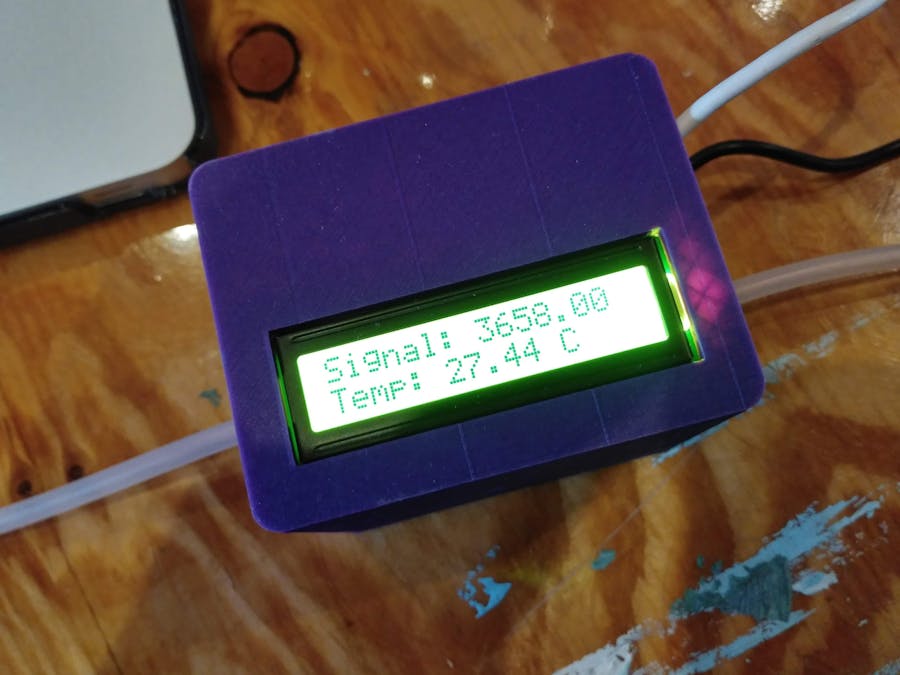
This module comprises the development of a flow-through photometer and temperature sensor unit for the determination of culture density and temperature.
Design Goals- Continuous density measurements
- Easy to (dis-)assemble
- Good culture density resolution
The culture is constantly pumped (peristaltic pump) through a glass tube where the OD is constantly measured. The photometer unit is based on a single module of the test tube photometer.
Main Components- Arduino or similar microcontroller You need something to read the analog input of the sensors in a measuring routine. I used an Arduino Nano.
- LCD display This one is optional but nice if you instantly want to see the measured values. It is useful for easy calibration and for discontinuous measurements with the photometer. You can use any available LCD which works well with the microcontroller. I used a standard HD44780 16x2 LCD Display and a I2C backpack.
- Measuring cell All the components you need to build a measuring cell are listed below.
- Pasteur pipette tube Be carful not to cut yourself while you prepare your pasteur pipette! Carefully remove the tip of the pipette and melt the edges with heat.
- Housing Well, this is optional too but it helps to keep the electronics save!
- Cell housing and housing cover You can find the 3D models in this repository. The housing has slots for the LED and the photodiode, which are fixed with the housing cover. If you do not have access to a 3D printer you can find service providers online. I printed it with standard black PLA and I recommend you to use black material, too, because it improves sensitivity of the system significantly. You might have to adjust the parameters of the housing to fit with your pasteur pipette tube!
- LED It is really important to use a high quality LED because it determines the wavelength you are measuring with. I used a 600 nm LED from Roithner LaserTechnik. If you prefer to measure at a different wavelength choose your LED accordingly!
- Photodiode This is the heart of the measuring cell. I used an opt101 from Texas Instruments because it contains an on-chip operational amplifier, and responds to light in the range of 300–1100 nm (linear dependence between 400–800 nm!). I added a external potentiometer to achieve a DC gain of up to 2 million volts per ampere to optimize the output voltages.
- Assemble the cell housing The housing consists out of two parts, the main body and a sleeve. There are two respective holes in the main body in which you can place the sensor and the LED. Slowly pull the sleeve over the main body with the LED and Sensor pins sticking out (see picture above). Please remember the sensor orientation for the correct wiring of the pins!
- Wiring Now you can start and solder wires to the sensor an LED pins. If you have problems soldering the sensor pins with the housing assembled you can remove the sensor, solder the wires and then assemble the housing. But then you might have to use some force to fit the soldered pins through the gaps. I labeled each wire to make it easier for me to connect them later.
You should end up with five wires from the sensor:
Power (V, pin 1)
Input/Additional Feedback (-In, pin 2)
Power/Ground (-V, pin 3)
Output (Output, pin 5)
Input/Ground (Common, pin 8)
- Connect it to the microcontroller Connect sensor pin 1 to 5V, pin 3 and 8 to ground. Sensor pin is connected to pin 5 with a potentiometer (or 1 MΩ resistor) in between (see circuit diagram on the right). You can now connect the sensor output (pin 5) to any analog input pin of your microcontroller and you are ready to measure light. Speaking of light, you still have to connect the LED with one of the digital output pins of the microcontroller to switch the light on and off.
- Insert the pasteur pipette tube Attach tubing to the smaller end of the pasteur pipette tube and insert it into the measuring cell. Try and position it completely inside the cell. The tube should be fixed inside (conical ending)!
- Assemble the complete module Insert the measuring cell into the housing and attach the LCD display to the housing lid. Connect the LCD and the temperature sensor to the microcontroller and arrange everything inside the housing.
The finished module can be attached to any peristaltic pump which fits the tube size (we used 6 mm tubing). Both ends of the tubing are inserted into the culture and the liquid should be pumped through the measuring cell. For data transfer the microcontroller can be connected to a single-board computer via a serial connection.


Comments