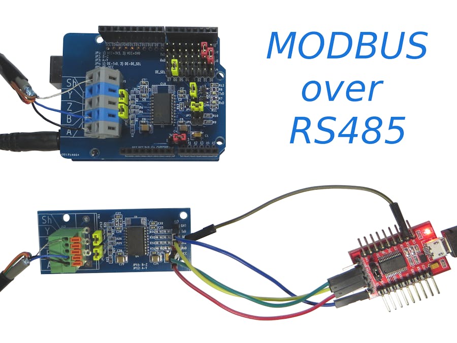
I have long had an idea about writing an article on the RS-485 interface. Initially, I planned to just transfer data (bytes). But once I came across an interesting project on ModBus:https://create.arduino.cc/projecthub/hwhardsoft/how-to-use-modbus-with-arduino-6f434b?ref=search&ref_id=rs485&offset=4
Thanks to the author of this project. I repeated his project, but with another shield, with another test program that does not work in Windows, but in Linux from the command line (there is also an option for Windows). I will not repeat the theory (I hope that you are familiar with it), because in the previous article, it is well described. Immediately proceed to the project.
ComponentsComponents that I used in the project:
Jumper positions are shown in photos.
SoftwareYou must first download and install the ModBus library for Arduino:
https://github.com/angeloc/simplemodbusng
Then upload the next sketch to Arduino:
/*
*  Test program for Arduino RS422/RS485 Shield
*  Version 1.0
*  Copyright (C) 2018  Hartmut Wendt  www.zihatec.de
*
*  (based on sources of https://github.com/angeloc/simplemodbusng)
*
*
*  This program is free software: you can redistribute it and/or modify
*  it under the terms of the GNU General Public License as published by
*  the Free Software Foundation, either version 3 of the License, or
*  (at your option) any later version.
*
*  This program is distributed in the hope that it will be useful,
*  but WITHOUT ANY WARRANTY; without even the implied warranty of
*  MERCHANTABILITY or FITNESS FOR A PARTICULAR PURPOSE.  See the
*  GNU General Public License for more details.
*
*  You should have received a copy of the GNU General Public License
*  along with this program.  If not, see <http://www.gnu.org/licenses/>.
*/
#include <SimpleModbusSlave.h>
#define  ledPin  12 // onboard led
#define  buttonPin  7 // push button
/* This example code has 9 holding registers. 6 analogue inputs, 1 button, 1 digital output
  and 1 register to indicate errors encountered since started.
  Function 5 (write single coil) is not implemented so I'm using a whole register
  and function 16 to set the onboard Led on the Atmega328P.
  The modbus_update() method updates the holdingRegs register array and checks communication.
  Note:
  The Arduino serial ring buffer is 128 bytes or 64 registers.
  Most of the time you will connect the arduino to a master via serial
  using a MAX485 or similar.
  In a function 3 request the master will attempt to read from your
  slave and since 5 bytes is already used for ID, FUNCTION, NO OF BYTES
  and two BYTES CRC the master can only request 122 bytes or 61 registers.
  In a function 16 request the master will attempt to write to your
  slave and since a 9 bytes is already used for ID, FUNCTION, ADDRESS,
  NO OF REGISTERS, NO OF BYTES and two BYTES CRC the master can only write
  118 bytes or 59 registers.
  Using the FTDI USB to Serial converter the maximum bytes you can send is limited
  to its internal buffer which is 60 bytes or 30 unsigned int registers.
  Thus:
  In a function 3 request the master will attempt to read from your
  slave and since 5 bytes is already used for ID, FUNCTION, NO OF BYTES
  and two BYTES CRC the master can only request 54 bytes or 27 registers.
  In a function 16 request the master will attempt to write to your
  slave and since a 9 bytes is already used for ID, FUNCTION, ADDRESS,
  NO OF REGISTERS, NO OF BYTES and two BYTES CRC the master can only write
  50 bytes or 25 registers.
  Since it is assumed that you will mostly use the Arduino to connect to a
  master without using a USB to Serial converter the internal buffer is set
  the same as the Arduino Serial ring buffer which is 128 bytes.
*/
// Using the enum instruction allows for an easy method for adding and
// removing registers. Doing it this way saves you #defining the size
// of your slaves register array each time you want to add more registers
// and at a glimpse informs you of your slaves register layout.
//////////////// registers of your slave ///////////////////
enum
{
 // just add or remove registers and your good to go...
 // The first register starts at address 0
 ADC0,
 ADC1,
 ADC2,
 ADC3,
 ADC4,
 ADC5,
 LED_STATE,
 BUTTON_STATE,
 TOTAL_ERRORS,
 // leave this one
 TOTAL_REGS_SIZE
 // total number of registers for function 3 and 16 share the same register array
};
unsigned int holdingRegs[TOTAL_REGS_SIZE]; // function 3 and 16 register array
////////////////////////////////////////////////////////////
void setup()
{
 /* parameters(long baudrate,
               unsigned char ID,
               unsigned char transmit enable pin,
               unsigned int holding registers size,
               unsigned char low latency)
    The transmit enable pin is used in half duplex communication to activate a MAX485 or similar
    to deactivate this mode use any value < 2 because 0 & 1 is reserved for Rx & Tx.
    Low latency delays makes the implementation non-standard
    but practically it works with all major modbus master implementations.
 */
 modbus_configure(115200, 1, 6, TOTAL_REGS_SIZE, 0);
 pinMode(ledPin, OUTPUT);
 pinMode(buttonPin, INPUT);
}
void loop()
{
 // modbus_update() is the only method used in loop(). It returns the total error
 // count since the slave started. You don't have to use it but it's useful
 // for fault finding by the modbus master.
 holdingRegs[TOTAL_ERRORS] = modbus_update(holdingRegs);
 for (byte i = 0; i < 6; i++)
 {
   holdingRegs[i] = analogRead(i);
   delayMicroseconds(50);
 }
 byte buttonState = digitalRead(buttonPin); // read button states
 // assign the buttonState value to the holding register
 holdingRegs[BUTTON_STATE] = buttonState;
 // read the LED_STATE register value and set the onboard LED high or low with function 16
 byte ledState = holdingRegs[LED_STATE];
 if (ledState) // set led
 {
   digitalWrite(ledPin, HIGH);
 }
 else if (ledState == 0) // reset led
 {
   //digitalWrite(ledPin, LOW);
   holdingRegs[LED_STATE] = 0;
 }
}
I did not connect the button and the LED (as in the previous project), for me it was enough to get an answer in the terminal window (which will be shown later).
Download to the computer and unpack the following file (for Linux):
https://www.modbusdriver.com/downloads/modpoll.tgz
For OS Windows download to the computer and unpack the following file:
https://www.modbusdriver.com/downloads/modpoll.zip
Open a terminal. In the terminal, change the directory:
cd ~/.../ModBus/modpoll/linux_x86-64
(if you have 64-bit operating system)or
cd ~/.../ModBus/modpoll/linux_i386
(if you have a 32-bit operating system)
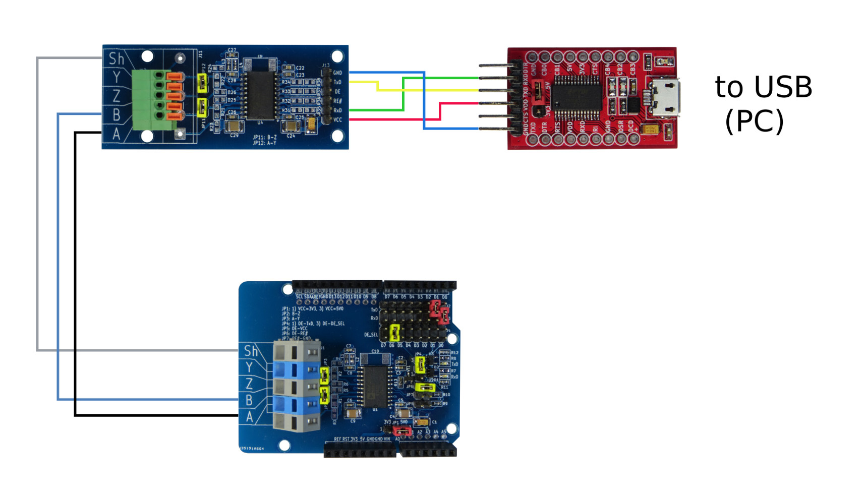
AssemblyConnection is carried out according to the following scheme:
USB to TTL Serial Adapter connects to the USB port of the PC (my port ttyUSB0).
In the terminal type the command:
./modpoll -b 115200 -d 8 -p none /dev/ttyUSB0 -a 1 -r 1 -c 8 -t 4 -l 1000
After entering which (if everything is properly connected), the received information from Arduino will be displayed in the terminal window:
Command list (from the README.txt file):
    _________________________________________________________________
Usage
Usage: modpoll [OPTIONS] SERIALPORT|HOST [WRITEVALUES...]
Arguments:
SERIALPORT    Serial port when using Modbus ASCII or Modbus RTU protocol
             COM1, COM2 ...                on Windows
             /dev/ttyS0, /dev/ttyS1 ...    on Linux
HOST          Host name or dotted IP address when using MODBUS/TCP protocol
General options:
-m ascii      Modbus ASCII protocol
-m rtu        Modbus RTU protocol (default if SERIALPORT contains /, \\ or COM)
-m tcp        MODBUS/TCP protocol (default otherwise)
-m udp        MODBUS UDP
-m enc        Encapsulated Modbus RTU over TCP
-a #          Slave address (1-255 for serial, 0-255 for TCP, 1 is default)\n
-r #          Start reference (1-65536, 1 is default)
-c #          Number of values to poll (1-125, 1 is default)
-t 0          Discrete output (coil) data type
-t 1          Discrete input data type
-t 3          16-bit input register data type
-t 3:hex      16-bit input register data type with hex display
-t 3:int      32-bit integer data type in input register table
-t 3:mod      32-bit module 10000 data type in input register table
-t 3:float    32-bit float data type in input register table
-t 4          16-bit output (holding) register data type (default)
-t 4:hex      16-bit output (holding) register data type with hex display
-t 4:int      32-bit integer data type in output (holding) register table
-t 4:mod      32-bit module 10000 type in output (holding) register table
-t 4:float    32-bit float data type in output (holding) register table
-i            Slave operates on big-endian 32-bit integers
-f            Slave operates on big-endian 32-bit floats
-e            Use Daniel/Enron single register 32-bit mode
-0            First reference is 0 (PDU addressing) instead 1
-1            Poll only once only, otherwise every poll rate interval
-l            Poll rate in ms, (1000 is default)
-o #          Time-out in seconds (0.01 - 10.0, 1.0 s is default)
Options for MODBUS/TCP, UDP and RTU over TCP:
-p #          IP protocol port number (502 is default)
Options for Modbus ASCII and Modbus RTU:
-b #          Baudrate (e.g. 9600, 19200, ...) (19200 is default)
-d #          Databits (7 or 8 for ASCII protocol, 8 for RTU)
-s #          Stopbits (1 or 2, 1 is default)
-p none       No parity
-p even       Even parity (default)
-p odd        Odd parity
-4 #          RS-485 mode, RTS on while transmitting and another # ms after
    _________________________________________________________________
I hope the article was useful for you. Thanks for attention.


_ztBMuBhMHo.jpg?auto=compress%2Cformat&w=48&h=48&fit=fill&bg=ffffff)


Comments
Please log in or sign up to comment.