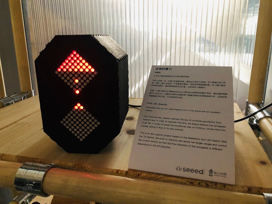
Graduates who do not make Newton turn in his grave are not excellent makers.
One historical day, Newton derived the law of universal gravitation from Kepler's law. In order to maintain this law, we always believe that all apples must fall. In order to break this traditional way of thinking, I broke time into pieces, letting it flow in its own journey.
This is an anti-gravity project based on the Seeeduino and LED Matrix. With the Tilt Switch, the built-in mercury can sense two angle ranges and control the current switch, so that the flow direction of the hourglass is different depending on the tilt direction.
My project is an hourglass based on 2 red LED Matrix and Tilt Sensor for balance detection on the Seeeduino Lotus platform. While struggling to recreate a realistic-looking hourglass, I have learned how to operate the laser cutter and to use the Grove - Tilt Sensor to control the 2 LED Matrixes (which requires 2 different MCUs).
LASER CUTTINGFor laser cutting, you can easily change the 3D design using Adobe Illustrator/AutoCAD or SolidWorks, where you will get a document with.sldprd/.drw/.dxf document suffix. Based on the different lines and colors used, you can define how deep the cut is, hollow areas of the model, etc., bringing you a 1:1 image reference before starting to cut the wood pieces with the laser cutter.
When you have a general idea of how you want the case to look like, this is a useful website to help you start designing.
https://www.festi.info/boxes.py/index.html
This website enables users to go through numbers of boxes, accessories or shelf designs, then download the document free of charge. This simplifies the design process greatly, making it less tedious than to design the entire box from scratch.
CODING/PROGRAMMINGBefore setting off to combine two different codes (for each part), you should first learn how to run the display effect that you are expecting without using sensors. Afterward, you can then combine the code for the sensor with the code for the display.
For instance, I was told that I need to figure out the performance of the LED Matrix in order to finalize the code for my hourglass. I did so and it helped me to understand the code better, enabling me to move ahead with my project.
https://xantorohara.github.io/led-matrix-editor/
This is an online Matrix editor, where you can tap to turn on and off and update the code for previewing. Then, COPY AND PASTE the code to the Arduino IDE, magic happens!
It has a total of 2 emoji that it needs to display, setting it with emoji 1/2/3/4[]. So my logic is that:
Matrix 1 runs Emoji1[];
Matrix 2 runs Emoji2[].
Emoji 1[]:
Emoji 2[];
So I pretty much got all the code I needed for the Matrix before we step into Tilt Sensor.
Hello Tilt Sensor,
The specifications of the module tell me that it is a switch made by mercury by detecting whether the module is upright. It is vital to know the exact positions for “up” and “down”.
Run appendix code 1, and in the serial monitor, it will define how it is connected or disconnected.
My logic is that when it is connected:
- If Tilt Sensor ON, then
Matrix 1 runs Emoji1[];
Matrix 2 runs Emoji2[].
- If Tilt Sensor OFF, then
Matrix 1 runs Emoji3[];
Matrix 2 runs Emoji4[].
Define the INPUT of the tilt Sensor:
pinMode(5, INPUT);
During the coding I met some recurring errors:
If this occurs in Arduino/Seeeduino Lotus:
avrdude: stk500_recv(): programmer is not responding
Try this:
Long press the reset button so that you can stop the program shortly, and it will get back to work when you re-open the Arduino IDE.
After I got the LED Matrix to light up, I realized that it is not easy to have 2 I2C Matrixes to run different patterns simultaneously
Hence, I need to find out the 2 addresses of those Metrix and Define them separately. ->
I gotta do some soldering, let’s have it!
Appendix Code 1:
Serial
void setup()
{
pinMode(5, INPUT);
}
void loop()
{
if (digitalRead(5)==HIGH)
{
digitalWrite(1);
}
}


Comments
Please log in or sign up to comment.