


Hardware components | ||||||
| × | 1 | ||||
| × | 1 | ||||
| × | 1 | ||||
| × | 1 | ||||
 |
| × | 1 | |||
| × | 1 | ||||
| × | 1 | ||||
 |
| × | 1 | |||
| × | 1 | ||||
| × | 1 | ||||
| × | 1 | ||||
 |
| × | 1 | |||
| × | 1 | ||||
| × | 1 | ||||
Software apps and online services | ||||||
 |
| |||||
Hand tools and fabrication machines | ||||||
 |
| |||||
 |
| |||||
| ||||||
What Do I Build Next? A Limited Edition Arduino Uno Mini Robot using a long-forgotten Sainsmart 4 wheeled chassis, I received an email from the Arduino Store or was it The PiHut? and immediately clicked the link to BUY, only $45.... yikes it better be special.
This Uno Mini is very tiny, with that said, it uses pin connectors with a 1.27mm pitch, the standard connector is 2.54mm. Same pinouts ? I overlooked what the pitch size meant.
My first step was to test and prep the Arduino Uno Mini with the standard "blink.ino" code example.
I next needed to solder an external power connector/wires to this board so I could power from my battery pack.
Standard dupont jumper leads are designed for the 2.54mm pitch connector, I soon found out that no one offered dupont jumper wires in the 1.27mm pitch size.
My initial testing with a servo was promising using the 2.54mm wires, but putting these 2.54mm jumpers into the smaller connector was difficult and nearly impossible when using adjacent slots. Ingenuity!!, I would just slightly bent the wires' protruding wire tip over slightly to a 45* angle and now pins could be placed side by side. SOLVED.... not.
I actually broke the end connector on pin 0, and also had an issue with plastic covering for each connector came off the metal pin that was soldered to UNO Mini circuit board. Mind you, As I added more jumpers wires and removed them these mini 1.27mm connector metal inserts became loose.
I had another "light bulb moment", Amazon must sell a 1.27mm pitch connector that I would solder my jumper leads onto thus creating a "Professional looking but specialized connector".
Off to Amazon: first a straight/inline connector
and Right angled
they were delivered in two days
I next cut 18 standard 2.54mm dupont jumpers in half and stripped the cut end wires so that I could "tin" with solder before attaching to these 1.27mm pitch connectors. I then attempted to "tin" these 1.27mm pitch connectors and after creating a solder mess with shorted pins and a melted plastic connector and jumper wires that just wouldn't solder in place. (and yes I did use flux and tried different solder).
Finally, after a half hour, I decided to remove the 2.54mm plastic shell from my standard dupont wires and put heat shrink over the exposed metal pins to prevent side by side shorting.
As for the very cheap all metal, Sainsmart 4 wheeled chassis that has long been discontinued on Amazon or Jameco.
" SainSmart 4WD Drive Aluminum Mobile Robot Platform for Arduino – SainSmart.com" I purchased sometime in 2018 to be built following this links'
Some assembly steps were from DFRobot's Pirate 4WD ROB03 kit.
" https://image.dfrobot.com/image/data/ROB0003/ROB03-Instruction%20MannualV2.0.pdf "
" (3780) MKme Lab - YouTube" by Eric William " Robotics – mkme.org "
" (3780) Arduino Autonomous 4WD Robot / Mars Rover Projects - YouTube"
MKme Labs as he developed his code. " (3780) Arduino Sainsmart 4WD Robot Programming - YouTube" and tried to correct and troubleshoot defective Ultrasonic sensor and kit contents.
I actually used his code as the basis for this project but I would not use the Arduino Mega 2560 that he used that was created by Scott Beasley.
" GitHub - MKme/Arduino-4WD-Sainsmart-Robot: Arduino controlled 4WD robot "
I also followed this build link "
Simple Multi-mode 4wd Rover JR-001 : 15 Steps (with Pictures) - Instructables ".
I didn't really, or at all change either code in the final build, but I needed to troubleshoot my Ultrasonic sensor "not that it was defective, but my jumpers were not seated or were shorting each other.
My basic wiring followed the Arduino code:
HC-SR04 Echo pin to Arduino Uno Mini pin 8
HC-SR04 Trigger pin to Arduino Uno Mini pin 3
Servo Signal pin to Arduino Uno Mini pin 4
L298N AIN1 pin to Arduino Uno Mini pin 5
L298N AIN2 pin to Arduino Uno Mini pin 6
L298N BIN1 pin to Arduino Uno Mini pin 9
L298N BIN2 pin to Arduino Uno Mini pin 11
Mode Selection pin to Arduino Uno Mini pin 2
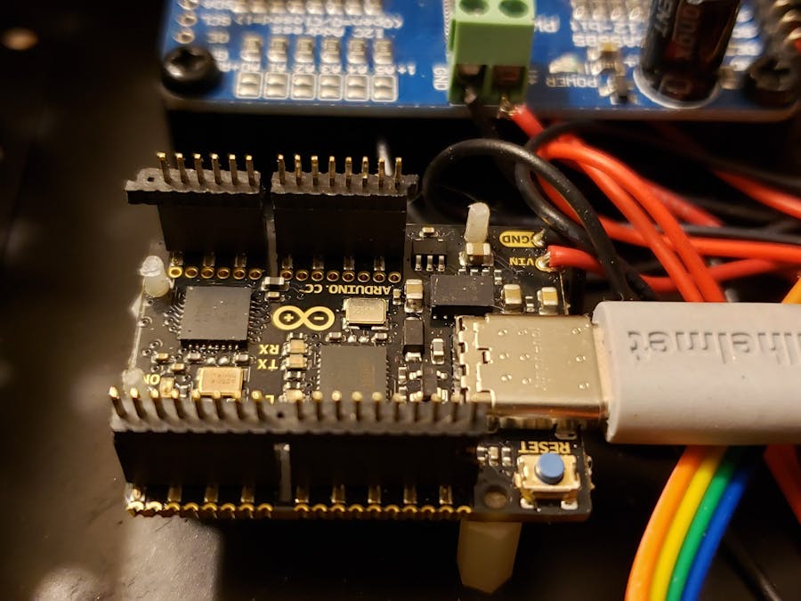
All 5V and Ground points came from those available on the 16-Channel PCA9685 Servo controller board
The 16-Channel PCA9685 Servo controller board was connected to the UNO Mini 's SDA, SCL, VCC, VIN, and GND PINS
5v and Ground wires were connected from 2x3.7vdc 18650 battery holder wires and the PCA9685 board as well as to the Arduino Uno Mini's power connection that I needed to solder in place to connect to my project. The PCA9685 board was a convenient method to have addition power and ground ports as well as add additional I2C capability if I choose to add additional servos or add a Raspberry Pi.
The most troublesome part of this build besides my wiring jumpers issues was to find a document that had the " mode switch" and battery recharge plug documented. I found this excerpt on the "Instructables.com" website
"Simple Multi-mode 4wd Rover JR-001 : 15 Steps (with Pictures) - Instructables " by JSCOTTB.
Wiring the Mode SwitchNOTE: You will need solder and a soldering iron for this step.
Take three of the Female to Female jumper wires and remove the connector from one end of each wire. Strip back the wires about 3mm long (@1/8th of an inch) and tin them with solder and a soldering iron. Then tin the three terminals on the switch as well. Now solder a wire to each terminal on the switch. See the picture for more details.
After the wires have been soldered on -
Connect the CENTER wire of the switch to PIN 2 on the sensor shield
- Connect the CENTER wire of the switch to PIN 2 on the sensor shield
Connect the RIGHT wire of the switch to a VCC line on the sensor shield
- Connect the RIGHT wire of the switch to a VCC line on the sensor shield
Connect the LEFT wire of the switch to a GND line on the sensor shield
- Connect the LEFT wire of the switch to a GND line on the sensor shield
The wonderful thing about this robot, is it is simple and adaptable... many code and project and videos are available.
My build:
Overall, this was a simple 1 hour build without the three days of frustration with soldering the 1.27mm pins. Did I say that I also contacted Arduino Tech Support about the lack of Vendor support for this "Limited Edition Arduino Uno Mini" and its 1.27mm pitch connector layout, their response was not helpful but suggested that it was clearly stated "Limited Edition Arduino Uno Mini". It also wasn't just its pitch pin connector, even the mounting holes were smaller than my smallest standard stand-off columns but I did manage.
Well lessons learned, smaller is not better.
Now, I have to still use a glue-stick to permanently attach and a fix these wires to the headers because they keep slipping out and also modify the charging port to allow charging and not have power to the Robot and I'll add a 2nd "Mode Switch" that will be used to switch ON/OFF the robot.
The Ultrasonic Sensor came unscrewed in last video so I'll also need a longer screw for that as well.
I also found that the quality of the crimp connector on the 16-channel PWM servo board is bad and wires do not insert correctly or completely into opening before screws tighten onto them. I have other of these.
I will also slow down the motors' drive speed which is too fast for the code example, most likely a different gear ratio of my motors and "original coders" motors.
I didn't include the "pitches.h" code and a speaker so this unit does not have sound or tones...yet.
Finally, at some point I'll add the Bluetooth Sensor to this and possibly a WIFI Camera to really utilize the MARS ROVER software with feedback to my PC.


Comments
Please log in or sign up to comment.