While developing and deploying wireless applications and sensor networks is mandatory to assert the wireless link, to try and estimate the maximum range between two devices and to prevent link loss due to rain, obstacles, fading, etc.
Normally you would need to include in your toolbox, besides a sniffer and spectrum analyser (such as this one), at least one transmitter and receiver, and pack a laptop to read and store the results, unless purchasing a kit properly prepared to do this, like the CC2538dk or the CC1120dk around 250€-300€ approx.
As I grew tired of packing my laptop and having to rush open field testing to cope with my discharging battery, I opted to prepare my own field test setup just packing the essentials, for a lightweight test spree.
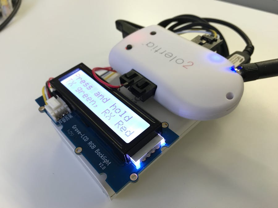
The componentsAs I primarily work with RE-Mote platforms both in the 2.4GHz and 863-950MHz bands, I threw in the mix a commercial USB battery charger I normally use when travelling, and the Sparkfun's LCD with RGB backlight.
The LCD works over I2C, the library was already ported in Contiki by me (see rgb-bl-lcd.c) and is powered over 5V (but luckily the I2C has a 3.3V logic).
As the RE-Mote works using a 3.3V logic but can be powered over USB at 5V, I powered the LCD from the RE-Mote over the D+5.1 pin (see above). The LCD I2C pins (SDA and SCL) are connected to the RE-Mote over the I2C.SDA and I2C.SCL pins as expected.
The battery charger is an USB battery with 6000mAh capacity, plenty of juice to last days of testing. The only drawback is having to either continuously press the power on button, or disable the RE-Mote's low power operation, else the battery "thinks" there's no connected device as the power consumption is too low.
The resultBelow is a video detailing the operation of the range test application.
When the application starts it will print information about the radio configuration. The current channel is displayed at the bottom row on the left, followed by the available channels and the transmission power (in dBm).
When the application starts it will start blinking the blue LED and instructions will be printed on the LCD.
Basically when long-pressing the user button (without releasing) it will toggle between the sender and receiver mode. The LCD will bright red when configured as receiver, or green when selected the transmitter mode.
When the user button is released the operation mode will be set (warning: if you need to change the operation mode, press the reset button and repeat). A single press on the user button will start the test.
I develop a simple application to wrap everything together, available as always in my Contiki's Github fork, look for the field-test-lcd branch.
git clone https://github.com/alignan/contiki
cd contiki && git checkout field-test-lcd
The application lives at examples/zolertia/zoul/range-test
If you look at the Makefile there are two compilations switches to consider:
ifdef WITH_LCD
CFLAGS += -DLCD_ENABLED=$(WITH_LCD)
endif

ifdef WITH_SUBGHZ
CFLAGS += -DRF_SUBGHZ=$(WITH_LCD)
endif
When compiling and programming the RE-Mote you can select to use either the 2.4GHz radio interface (CC2538) or the 868/915MHz radio (CC1200) (if adding WITH_SUBGHZ=1). If you include the WITH_LCD=1 argument to the compilation it will include the LCD display support, else if you don't have a LCD display you can still see the results over USB if connecting to the RE-Mote, by just using a micro-USB cable and putty or alike.
# Configure for 868MHz band
make range-test.upload WITH_SUBGHZ=1 WITH_LCD=1

or

# Configure for 2.4GHz band
make range-test.upload WITH_LCD=1
And that's it! have fun testing and enjoying the weather!


Comments
Please log in or sign up to comment.