


Hardware components | ||||||
 |
| × | 1 | |||
| × | 1 | ||||
| × | 1 | ||||
Software apps and online services | ||||||
 |
| |||||
Why we use an encoder along with DC motor?
The speed and position of a DC motor shaft can be controlled using the encoder readings. This is critical in many applications.
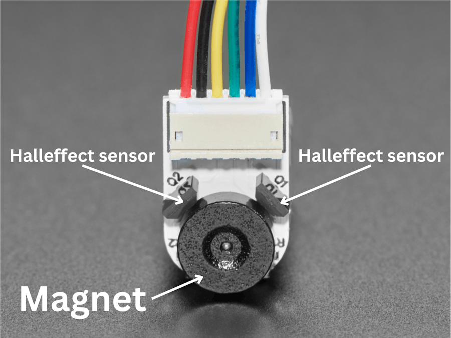
In this documentation we are dealing with magnetic encoders.
A magnetic encoder have a permanent magnet and two hall effect sensors
Consider the motor is not rotating the encoder pins generate logic 0.
Let's consider we have only one halleffect sensor
When the motor start rotating the hall effect sensor generate zeros and ones.
Here we can see a square wave. We count the number of rise occurs. We call this count as encoder tick values. For a single rotation of motor the encoder tick value is fixed. So by knowing the encoder tick values we can find the number of rotations of the motor shaft.
Consider an example,
Our motor encoder output rise 1000 times per a rotation of the motor shaft. Let we have counted 10000 rise in encoder output. Then we can calculate the number of rotation of the motor 10000/1000 = 10 rotations.
We now know how find the number of rotations of the shaft. How we will find the direction of rotation ? For that we use another halleffect sensor.
When the motor rotates in clockwise direction, Encoder pin A leads Encoder Pin B.
When the motor rotates in anticlockwise direction Encoder pin B leads encoder pin A.
Now lets implement this,
ImplementationHow will we count the rise in the encoder value. For that we use interrupt.
We will connect the encoder pin A to interrupt pin of microcontroller, We are using ESP32. All GPIOs of ESP32 can be configured as interrupts. For more info refer pinout of ESP32.
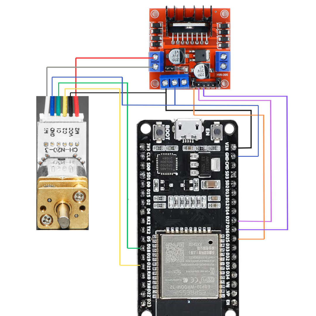
Pin connection
C1 - EncoderPin A - 18
C2- EncoderPin B - 21
Vcc- Vcc of encoder
Gnd- Gnd of encoder
M1- Motor pin 1
M2- Motor pin 2
Code
#define EncoderPinA 18
#define EncoderPinB 21
#define ForwardPin 27
#define BackwardPin 26
#define EnablePin 25
volatile long Encodervalue=0;
void setup() {
pinMode(ForwardPin,OUTPUT);
pinMode(BackwardPin,OUTPUT);
pinMode(EnablePin,OUTPUT);
pinMode(EncoderPinA, INPUT);
pinMode(EncoderPinB, INPUT);
attachInterrupt(digitalPinToInterrupt(EncoderPinA), updateEncoder, RISING);
Serial.begin(9600);
}
void loop() {
digitalWrite(ForwardPin,HIGH);
digitalWrite(BackwardPin,LOW);
analogWrite(EnablePin,255);
Serial.println(Encodervalue);
delay(100);
}
void updateEncoder()
{
if (digitalRead(EncoderPinA)> digitalRead(EncoderPinB))
Encodervalue++;
else
Encodervalue--;
}
Let's breakdown the code,
Pin definitions. Forwardpin and BackwardPin are used for controlling the direction. EnablePin is used for controlling the speed of the motor using pwm.
#define EncoderPinA 18
#define EncoderPinB 21
#define ForwardPin 27
#define BackwardPin 26
#define EnablePin 25
Encodervalue variable is used for counting the rise
volatile long Encodervalue=0;Defining the pin modes
pinMode(ForwardPin,OUTPUT);
pinMode(BackwardPin,OUTPUT);
pinMode(EnablePin,OUTPUT);
pinMode(EncoderPinA, INPUT);
pinMode(EncoderPinB, INPUT);
Initialization of interrupt. Whenever the EncoderPinA rises the updateEncoder function is exectuted.
attachInterrupt(digitalPinToInterrupt(EncoderPinA), updateEncoder, RISING);Update encoder compares the value of EncoderPinA and EncoderPinB and determines the direction of motor rotation and increment or decrement encodervalues accordingly. If the motor rotates clockwise encoder value in incremented and if the motor rotates in anticlockwise direction encoder value is decremented.
void updateEncoder()
{
if (digitalRead(EncoderPinA)> digitalRead(EncoderPinB))
Encodervalue++;
else
Encodervalue--;
}
Motor is rotated in forward direction and Encodervalues are printed on Serial monitor
void loop() {
digitalWrite(ForwardPin,HIGH);
digitalWrite(BackwardPin,LOW);
analogWrite(EnablePin,255);
Serial.println(Encodervalue);
delay(100);
}
Output
Encoder values are printed on the serial monitor.
Encoder value per rotation for a motor can be found on the datasheet. If it is not available you can find it by observing the encoder value on the serial monitor corresponding to the one revolution of the motor shaft. Here is the one way of doing so,
Pin connections
Make the connections as follows. Here we have connected encoder pins only
Upload the following code
#define EncoderPinA 18
#define EncoderPinB 21
volatile long Encodervalue=0;
void setup() {
pinMode(EncoderPinA, INPUT);
pinMode(EncoderPinB, INPUT);
attachInterrupt(digitalPinToInterrupt(EncoderPinA), updateEncoder, RISING);
Serial.begin(9600);
}
void loop() {
Serial.println(Encodervalue);
delay(100);
}
void updateEncoder()
{
if (digitalRead(EncoderPinA)> digitalRead(EncoderPinB))
Encodervalue++;
else
Encodervalue--;
}
Rotate the motor using your hands for one revolution and note down the encoder value printed on serial monitor.
For more accuracy rotate the motor for 10 or more revolutions and divide the corresponding encoder value with number of rotations made.
Reference1. Synchronizing Motor Position with Encoders, PID Control and Arduino


Comments
Please log in or sign up to comment.