This year the world famous 555 timer IC celebrates its 50th anniversary! A lot of things have happened with IC's since then but the 555 timer IC still has its following. Most designers know that today you can buy CMOS versions of the classic 555 timer if you need a timer for projects that have to save on power. However, not many seem to know about the CSS555 timer. This IC is very special in many ways. First of all, it is only uses 1/10th of the power that the otherwise low power CMOS 555 IC's use (e.g. TLC555). Second, the CSS555 has a built in EEPROM that allows you to program it to multiply the delay time by a factor from 1 (standard 555) to 1 million. This is fantastic as long time delays with 555 timers have always required the use of very large electrolytic capacitors. Thus, with the CSS555 you can skip that and stick to orders of magnitude smaller ceramic capacitors. That saves on spaces and makes the circuit more reliable in general. Take a look at the two capacitors in the photo below. The one to the left is a 10uF ceramic capacitor and the one to the right is a 1000uF electrolytic capacitor. With a regular 555 timer (e.g. NE555 or TLC555) and using the same time delay resistor, the larger electrolytic capacitor would give a time delay that is 100 times longer than the delay created by the much smaller ceramic capacitor. However, with a CSS555 timer you could program it to have a 1, 000, 000 multiplication factor. If you do that, it means that you can get a time delay from the smaller ceramic capacitor that is 10, 000 longer (!) than what the larger capacitor would give you with a regular 555 timer....
In addition to the CSS555 timer, there is the CSS555C timer that also has a built-in capacitor that you can program the value for (85-115 pF). That will allow you to fine-tune circuits with ease! In short, the CSS555/CSS555C timers are worth a look if you are into designing circuits that need a timer and runs for extended periods of time on battery power.
The Arduino based EEPROM programmerWhile it is nice to have the possibility to program the internal EEPROM in the CSS555/CSS555C, you also need something to program it with. You used to be able to purchase a programmer for these IC's (EZ-programmer) but in this article I will show you a simple way to program these IC's using an Arduino. I should mention that part of my program is based on code I found online written by Ron Spooner. Thank you Ron!! However, my code has some key timing differences and it extends the functionality to also include a verification feature. That way you know that the programming went well before you insert the programmed CSS555/CSS555C in a circuit.
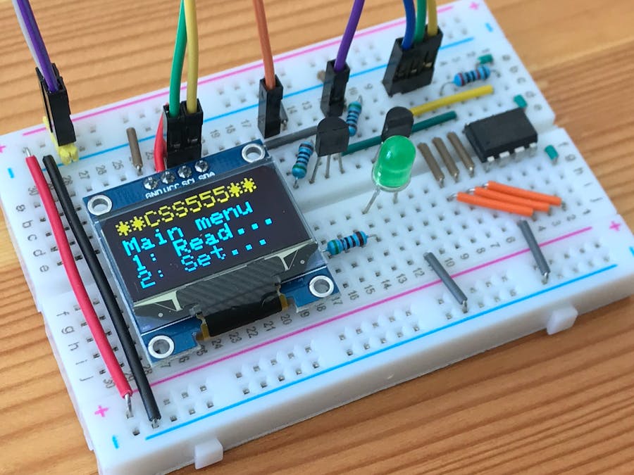
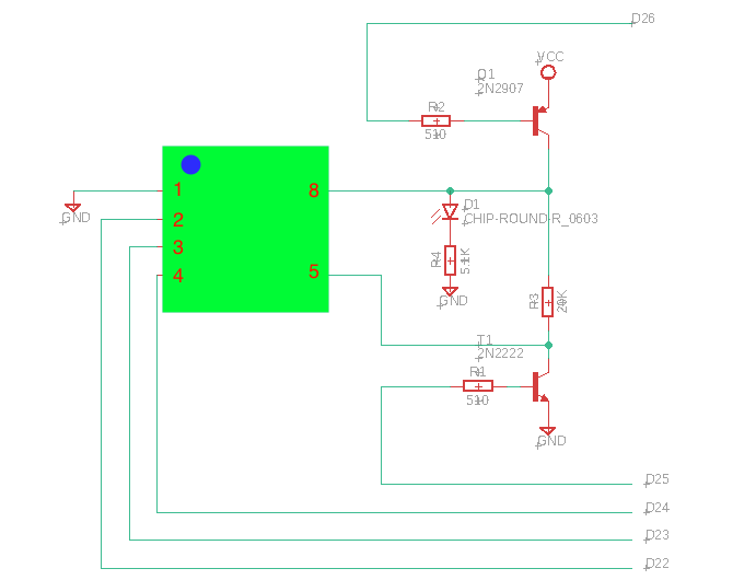
For this EEPROM project I have opted for a user interface based around an I2C OLED display and and a 4x4 keypad. I have also included a feature that controls the power to the CSS555/CSS555C so that you can hot-swap the CSS55/CSS555C without turning off the power to the Arduino. As a result, I have to use an Arduino Mega for this project as both the Uno and Nano lacks the number of digital pins we will need (1 extra pin needed).
In addition to the Arduino Mega, OLED display, and keypad, this project also uses two transistors (2N2222 and 2N2907), two 510 ohm resistors, one 5.1K resistor, and a green LED. The LED indicates when the power is on to the 555, which is briefly during read/write operations. When the LED is off it is safe to remove the CSS555/CSS555C.
The programmer is using a set of menus that will allow you to set all the parameters in the CSS555 and CSS555C IC's. In addition, it will also allow you to set external parameters (Ra, Rb, Cx) and it will automatically compute the delay time based on the settings. Also, every time you write to the EEPROM the settings are stored internally in the Arduino and recalled when you power up the Arduino the next time. That will save you from re-entering all values that you usually use.
When you use the programmer the following keys have special functions:
A) Go to the main menu
B) Skip to the next sub-category
C) Increase the value shown
D) Decrease the value shown
7) Decrease the value shown with a large jump
9) Increase the value shown with a large jump
#) Write to the EEPROM
The external parameters (Ra, Rb, and Cx) are selected from the E6 series. The resistors are in Kohm and can have values in the 100K-10M range. The capacitance is in pF and have values in the 10pF-10nF range. It can also be set to zero if no external capacitance is used. Please note however, that the software takes the internal parasitic capacitance into account (26 pF) automatically for all the computations. This parasitic value was found thru a series of experiments.
The internal capacitance (CSS555C only) can be set between 85pF and 115pF in increments of about 0.1pF (8 bits, 256 levels, 30pF range).
It only takes two bytes to fully configure the CSS555/CSS555C (configuration byte and capacitor byte). While that sounds easy, I quickly discovered that it is quite difficult. This is mostly due to the fact that there are typo's in the documentation (old version) for this IC that is related to the timing. But with help from the manufacturer and by looking at the signals using an oscilloscope I finally figured out how to get it all to work. Thus, I figured I can share my findings here as it might shine some light on the protocol for those how are interested in these timers.
The communication with the CSS555/CSS555C is a two step procedure for each byte that you will set or read (configuration byte and capacitance byte). First you send a command byte indicating what you want to do (set or read and what byte you refer to) and then you send the byte or read back a byte from the CSS555/CSS555C.
Setting a byte on the CSS555/CSS555CIn Fig. 1a below I show what the signals look like when we send the command byte 0001-0010 and then send the configuration byte 0000-1011. The important thing to note here is that the trigger happens on the positive edge (low-to-high) of the clock pulse for the command byte and the negative edge (high-to-low) for the configuration byte! I have marked the trigger points with vertical lines in the plots. It should also be pointed out that all bits are sent in reverse order when talking to the EEPROM (LSB first).
When we want to read a byte from the CSS555/CSS555C we first have to send a command indicating what we want to do and then listen to the byte that comes from the CSS555/CSS555C. In Fig. 1b below I show how that phase looks on the oscilloscope when we send the command byte 0001-0001 and then read back the byte 0000-1011. As before, note that the trigger happens on the positive edge (low-to-high) of the clock pulse when sending the command byte and the negative edge (high-to-low) when reading the byte from the CSS555/CSS555C.
In this project we have shown how to easily make an Arduino based EEPROM programmer for the CSS555/CSS55C timer IC's. The difference between the two timers is that the C-version also include a programmable capacitor that can be set to values from 85 to 115 pF.
However, during my experiments with both versions I discovered something really interesting. In my set-up the CSS555 version IC's actually have an internal parasitic capacitance of about 26 pF. But the values that you program for the C-version includes this value! Thus, in reality the programmable capacitance in the C-version can take values from 59 to 89 pF as the internal 26 pF (constant) is added to this value. This does not really matter but it is worth pointing out that the capacitance that you set for the C-version IC's is the total capacitance which includes the internal parasitic capacitance.
Finally, what makes these timers so great? In my case I am using the CSS555/CSS555C in a circuit that controls the power to an Arduino Nano based project. That way the project can run for many years (!!!) on a standard 9V battery... In Fig. 2 below is a screen dump from my bench multimeter that shows the total current draw during the sleep-cycle from the 9V battery that powers my Arduino Nano based project: 8.55uA!
Yes, you can accomplish similar and even better results using better suited micro-controllers in combination with various more or less advanced sleep modes in the code. But I wanted a simple way to use my standard Arduino Nano or Uno in projects that run on a 9V battery for extended periods of time. And with the help of a CSS555/CSS555C this can easily be accomplished. All without a single line of code with sleep modes or de-soldering of unnecessary components!
Questions or comments? Feel free to contact me at abaruk*@gmx.com (replace the 'b' in the address with the letter m and the star with the number one).
Update 1I have now been using this Arduino based EEPROM programmer for about two months. Over this time period I have probably programmed over a hundred CSS555 and CSS555C IC's and the programming procedure has worked every time! Well, that is not entirely true... It actually failed me once but that was because I had put the CSS555 in the wrong way (upside down)... To my big surprise this silly operator error did not cause the CSS555 to blow up! No, after I put the same CSS555 in the correct way I could successfully program it!
After a few more months of use I decided to design a custom PCB based on this design. I designed the PCB as a shield for an Arduino MEGA. Below are some pictures that show the results.


Comments
Please log in or sign up to comment.