In DC motor speed testing, the PWM is applied to motor and its duty cycle is varied from min to max. While applying PWM the actual RPM of DC motor is also measured and note down to see how motor speed (RPM) varies as PWM width varies. Along with this, the applied voltage to motor is also measured to see the motor speed at different applied voltage. Finely, after noting down all the values, the observation table is prepared for pulse width (duty cycle), applied voltage and motor speed in RPM. This table is used to prepare duty cycle->RPM graph or applied voltage->RPM graph of motor.
The given project demonstrates above example. It applies PWM to DC motor to vary its speed from min to max and max to min continuously and also measures following parameters
1) PWM width in %
2) Applied voltage to motor
3) Motor speed in RPM
It uses arduino UNO board to generate PWM and measure/calculate above 3 parameters. These parameters are displayed on 16x4 LCD. It is very easy to vary speed of DC motor using arduino. Arduino can generate PWM on its analog output pin and when it is applied to DC motor, its speed varies. So it is very simple and easy task. To measure RPM, opto-interrupt sensor MOC7811 is used. When motor completes 1 revolution, the sensor generates 1 pulse and such pulses are calculated by arduino to calculate RPM. So let us see how this is done. Lets start with circuit diagram first, followed by its descriptions and operation.
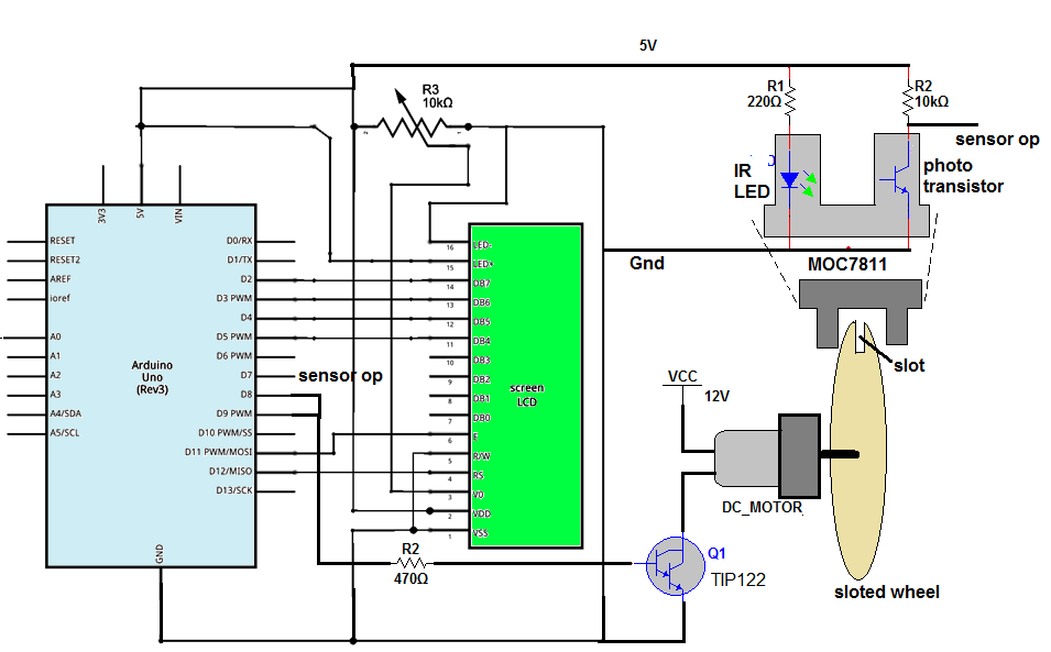
Circuit diagram:As shown in figure, the circuit is built using arduino UNO development board, 16x4 LCD, NPN Darlington transistor TIP122 and opto interrupt sensor MOC7811.
· The analog output pin 9 of arduino drives 12V@2000 RPM DC motor through TIP122. This pin is given to base input of TIP122 through current limiting resistor R2 and DC motor is connected to collector of TIP122
· The internal IR LED of MOC7811 is given forward bias using 5V supply form arduino board through current limiting resistor R1. Internal photo transistor is pulled up by resistor R4. The collector output of transistor is connected to digital pin 7 or arduino
· LCD data pins D4 to D7 are connected to digital pins 5, 4, 3 and 2 of arduino while control pins Rs and En are connected to 12 and 11. RW pin is connected to ground. Vcc pin and LED+ pin are connected to 5V supply from arduino board and Vss pin and LED- pins are connected to arduino board ground
· One pot is connected to Vee pin to vary contras of LCD
Circuit operation:· First the motor is given 12 V supply through external power supply. Next the arduino board, LCD and sensor is given supply through USB from PC / laptop
· Initially the LCD shows different parameters as
PWM ip:
PWM Duty:
PWM volt:
speed:
· Then arduino starts applying PWM to motor with maximum pulse width
· So motor will start rotating at maximum speed. Some time delay is provided to allow motor to attain full speed
· As the motor starts rotating, the slotted wheel attached to its shaft will also rotate
· The MOC7811 sensor is placed such a way that the slot of wheel passes through sensor air gap. Thus when motor rotates one full revolution, the slot passes through sensor gap. Due the slot in the wheel the IR light falls on photo transistor. So transistor conducts and generates negative pulse in collector output. Thus each rotation of motor produces pulse
· The frequency of these pulses is actually RPS (-revolution per second) of motor. To measure the frequency of this pulse first the ON time is measured then OFF time is measured and from these frequency is calculated as
Time period = Ton + Toff (in us)
Frequency= 1000000/time period
· This frequency is speed of motor in RPS. From this RPS, speed of motor is calculated in RPM as
RPM= 60×RPS
· The PWM input is varied from 250 to 100 in step of 15. That is directly displayed on LCD
· The ON time and OFF time of PWM output is also measured to calculate the PWM duty cycle as
PWM duty = [PWM_Ton / (PWM_Ton + PWM_Toff)] × 100
· Finally voltage applied to motor is calculate as
Voltage applied to motor = motor voltage × duty
= (12/100)× duty
· First the PWM input is decreased from 250 to 100 in 10 steps of 15 and then again it is increased from 100 to 250 and this cycle is repeated continuously
· So motor speed continuously decreases and then continuously increases. We can observe the change in motor speed that is displayed on LCD as speed in RPM
Thus the given project varies the speed of DC motor and also measures it accurately. It displays % of pulse width applied to motor along with applied voltage. So one can note down motor speed in RPM at different voltage and pulse width in observation table for further needs.


_ztBMuBhMHo.jpg?auto=compress%2Cformat&w=48&h=48&fit=fill&bg=ffffff)


Comments