I used the Arduino MKR1000 as the microcontroller to create my Pen Replacement system. I used the MKR1000 because it is wifi enabled and there is a great resource for connecting to Amazon DRS with an internet connected Arduino. Make sure that the Arduino software is updated completely before adding the AmazonDRS, AmazonJSON and Wifi101 resources. When I ran it with an older version of the Arduino software, I got a bunch of errors that prevented me from compiling the code.
The tutorial on the website: https://github.com/andium/AmazonDRS is very helpful but there are a couple notes that isn't mentioned that caused me some frustration. Within the Security Profile>Web Settings, make sure that you add https://www.getpostman.com/oauth2/callback to Allowed Return URLs. When it gets to the part about AmazonTokens.h, you need to remember to clear the refresh_token, the authorization_grant_code and the access_token before you run the authCodeGrant code to get the refresh_token. Besides that, the github resource is very well written and concise that covers almost everything that you need to get Amazon DRS setup on your MKR1000.
Before I set it up for the limit switches for my project I tested it with what the example suggested which was a single pushbutton onto pin 12. This was found in the examples under amazonDashButton example.
I wanted to use limit switches instead of photoresistors or a mass sensor for a couple reasons - photoresistors require analog inputs so if I wanted to scale the device to detect 24 pens instead of 5 then I would need a lot more analog inputs. Photoresistors would also require me to autoadjust the system based on outside light. If the system was in a drawer or someplace very dark, the photoresistor wouldn't do it's job very well. I didn't use a mass sensor because if a user stacks a bunch of stuff on top of the pens (like in an office environment) then there would be no indication about whether it was random stuff or something specific.
I bought some limit switches online that require 5VDC, ground and outputs a normally closes signal. Normally closed signals give a 5VDC signal when the limit switch isn't pressed and 0VDC when the switch is pressed. There is an LED on the switch to indicate when the switch is pressed.
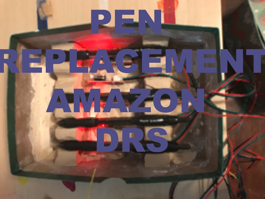
I used five limit switches and put them in a row so that each one lines up with a pen. I used quick drying clay to make a shape that would line up the pens with the limit switches. The limit switches were larger than I had initially hoped so because of that, I decided that this project was more of a proof of concept rather than a fully fledged project idea.
See the modified code that I wrote and the comments in the code for how my logic works. Below are images of the results are from running the code.
When the system requests a replacement, it asks Amazon to send an email to the user to notify them that the replenishment is being ordered and is on its way.


Comments