

Hardware components | ||||||
 |
| × | 1 | |||
| × | 1 | ||||
| × | 1 | ||||
 |
| × | 1 | |||
 |
| × | 1 | |||
| × | 1 | ||||
| × | 1 | ||||
Software apps and online services | ||||||
 |
| |||||
 |
| |||||
Hand tools and fabrication machines | ||||||
 |
| |||||
| ||||||
| ||||||
Biking at night is not only a driving hazard but also a biking hazard. I wanted to create a system that would be able to communicate to drivers and other bikers about when the biker is starting and stopping and when the biker is maintaining a particular speed.
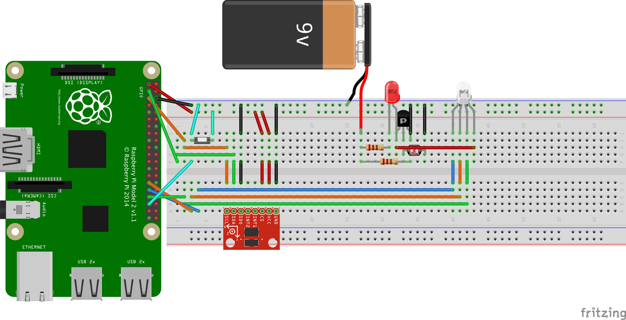
I wanted a system that could turn on the lights at night automatically so if the weather is particularly gloomy, the bike would automatically adjust to the darkness and turn on the LEDs. In order to do this I decided to use a photoresistor and designed a circuit where if the light intensity was low (which occurs when it is dark) to set the output to ~9V and if the light intensity was high (which occurs when it is sunny) to set the output to ~0V. This is done with a voltage divider circuit.
The RGB LED strip has four wires - white is for the 12V signal (a 9V battery was used), the red wire is for the !red (meaning that a 3.3V signal results in no red and a 0V signal results in red), blue and green wires are for the !blue and !green signals respectively.
For the accelerometer I followed the steps outlined in: https://ms-iot.github.io/content/en-US/win10/samples/I2CAccelerometer.htm only instead of using the Sparkfun accelerometer I used the ADXL345 from AC Electronics. The CS and the 3V3 wires are connected to the 3.3V signal. 5V and VS pins are left disconnected. GND is tied to ground. SCL was connected to the SCL pin on the Raspberry Pi. SDA on the accelerometer was connected to the SDA pin on the Raspberry Pi. SDO on the accelerometer was connected to ground. Once it was wired, the sample code given for the accelerometer was ran and it was found to be successful. The accuracy for the X-axis acceleration was 0.055G off which is acceptable for detecting starting and stopping but not very accurate if I wanted to calculate the speed.
The code is currently set to turn the LEDs green if the acceleration is greater than 0.25Gs (meaning 8 ft/s^2 of acceleration) and turn the LEDs red if the acceleration is less than -0.25Gs. Turns shouldn't matter as long as the accelerometer stays in the same orientation the entire time (by attaching it to the frame near the handlebar, this shouldn't be an issue).
For the RGB LED strip, a waterproof SMD RGB LED lighting strip was chosen. The specifications required for it to have a 12 V power source (a 9V battery was used instead and it seems to work fine) and for the colors to be activated by sending a 0V signal to each of the red, green and blue signals. Because there is no analog out pin on the raspberry pi, three GPIO pins were used to control red, green and blue.
A if/else statement was used to implement the three scenarios: if the bike is accelerating, turn the LEDs green, if the bike is decelerating, turn the LEDs red and if neither of those things occur (and it is still dark), turn the LEDs blue. This structure allows the drivers (and fellow bikers) to know when the biker is stopping, starting, and continuing to bike at a relatively constant speed. The photoresistor circuit is also used here in order to tell the system if it is daytime or not.
I added in a random mode when GPIO pin 26 (the button in the final circuit) is tied to ground and causes the circuit to start flash randomly in a color sequence until the button is pressed again which reverts back to the acceleration dependent mode.
The light sensing circuit was first built to turn on when light is on . The light sensing circuit is composed of: 2 resistors (one very small ~10 Ohms, and one relatively large ~100k Ohms), a photoresistor, an LED and an NPN transistor. The circuit shown in the diagram turns on the RGB strip when light is exposed to it. To simplify this circuit greatly for a dark sensing circuit I used a voltage divider with a resistor connected from the 9V signal to the photoresistor and the photoresistor tied to ground. The signal for the RGB LED strip is connected to the photoresistor/resistor connection. This means that when it's sunny, the resistance across the photoresistor is almost 0 and the voltage to the RGB LED strip is also almost zero. When it is dark, the resistance across the photoresistor is much higher than the resistor and the voltage to the RGB LED strip is nearly 9V.
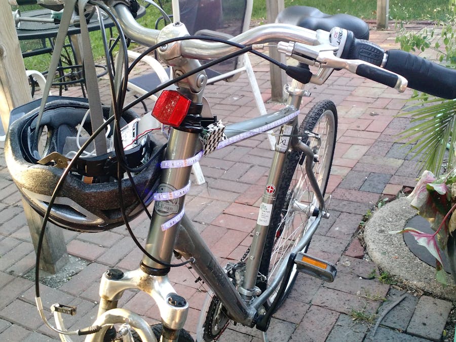
The circuit was then wire wrapped in order to save space.
Because I could only deploy the code to the system within the range of my wifi (because I'm using a desktop) I created a video to show how the system works. When circuit is orientated at a forward angle this is equivalent to accelerating forward and turns the circuit green. When the circuit is angled in the opposite angle it is equivalent to decelerating (stopping) and it turns the circuit red. When the button is pressed the circuit rotates through colors as explained above.
The system was attached to the bike and setup with the raspberry pi and battery in my helmet and the accelerometer circuit attached to the frame closest to the handle bar.

Code V1.0
C#// So I directly modified the Accelerometer code that was provided from Microsoft so that I could make my system work
// Not all of these 'using' commands were in the Accelerometer code, I added a few of them so I could make the lights/light sensor work as well
using System;
using System.Threading;
using Windows.UI.Xaml.Controls;
using Windows.Devices.Enumeration;
using Windows.Devices.I2c;
using Windows.Devices.Spi;
using Windows.Devices.Gpio;
using Windows.UI.Xaml;
using Windows.UI.Xaml.Media;
namespace Accelerometer
{
struct Acceleration
{
public double X;
public double Y;
public double Z;
};
enum Protocol { NONE, SPI, I2C};
/// <summary>
/// Sample app that reads data over either I2C or SPI from an attached ADXL345 accelerometer
/// </summary>
public sealed partial class MainPage : Page
{
/* Important! Change this to either Protocol.I2C or Protocol.SPI based on how your accelerometer is wired */
private Protocol HW_PROTOCOL = Protocol.I2C;
private const byte ACCEL_REG_POWER_CONTROL = 0x2D; /* Address of the Power Control register */
private const byte ACCEL_REG_DATA_FORMAT = 0x31; /* Address of the Data Format register */
private const byte ACCEL_REG_X = 0x32; /* Address of the X Axis data register */
private const byte ACCEL_REG_Y = 0x34; /* Address of the Y Axis data register */
private const byte ACCEL_REG_Z = 0x36; /* Address of the Z Axis data register */
private const byte ACCEL_I2C_ADDR = 0x53; /* 7-bit I2C address of the ADXL345 with SDO pulled low */
private const byte SPI_CHIP_SELECT_LINE = 0; /* Chip select line to use */
private const byte ACCEL_SPI_RW_BIT = 0x80; /* Bit used in SPI transactions to indicate read/write */
private const byte ACCEL_SPI_MB_BIT = 0x40; /* Bit used to indicate multi-byte SPI transactions */
private I2cDevice I2CAccel;
private SpiDevice SPIAccel;
private Timer periodicTimer;
public MainPage()
{
this.InitializeComponent();
/* Register for the unloaded event so we can clean up upon exit */
Unloaded += MainPage_Unloaded;
/* Initialize the I2C bus, accelerometer, and timer */
InitAccel();
InitGPIO();
}
// This adds the RGB code taken from the other Microsoft tutorial on lighting a RGB LED
private void InitGPIO()
{
var gpio = GpioController.GetDefault();
// Show an error if there is no GPIO controller
if (gpio == null)
{
redpin = null;
bluepin = null;
greenpin = null;
return;
}
redpin = gpio.OpenPin(REDLED_PIN);
bluepin = gpio.OpenPin(BLUELED_PIN);
greenpin = gpio.OpenPin(GREENLED_PIN);
redpin.Write(GpioPinValue.High);
redpin.SetDriveMode(GpioPinDriveMode.Output);
bluepin.Write(GpioPinValue.High);
bluepin.SetDriveMode(GpioPinDriveMode.Output);
greenpin.Write(GpioPinValue.High);
greenpin.SetDriveMode(GpioPinDriveMode.Output);
// This is the code taken from 'Button' tutorial also from Microsoft's tutorial page. This is for the photosensor so the lights will turn on automatically
buttonPin = gpio.OpenPin(BUTTON_PIN);
if (buttonPin.IsDriveModeSupported(GpioPinDriveMode.InputPullUp))
buttonPin.SetDriveMode(GpioPinDriveMode.InputPullUp);
else
buttonPin.SetDriveMode(GpioPinDriveMode.Input);
// Set a debounce timeout to filter out switch bounce noise from a button press
buttonPin.DebounceTimeout = TimeSpan.FromMilliseconds(50);
}
private void InitAccel()
{
/* Initialize the protocol and accelerometer */
switch (HW_PROTOCOL)
{
case Protocol.SPI:
InitSPIAccel();
break;
case Protocol.I2C:
InitI2CAccel();
break;
case Protocol.NONE:
Text_Status.Text = "Please change the HW_PROTOCOL variable to either I2C or SPI";
break;
default:
break;
}
}
/* Initialization for I2C accelerometer */
private async void InitI2CAccel()
{
try
{
var settings = new I2cConnectionSettings(ACCEL_I2C_ADDR);
settings.BusSpeed = I2cBusSpeed.FastMode; /* 400KHz bus speed */
string aqs = I2cDevice.GetDeviceSelector(); /* Get a selector string that will return all I2C controllers on the system */
var dis = await DeviceInformation.FindAllAsync(aqs); /* Find the I2C bus controller devices with our selector string */
I2CAccel = await I2cDevice.FromIdAsync(dis[0].Id, settings); /* Create an I2cDevice with our selected bus controller and I2C settings */
if (I2CAccel == null)
{
Text_Status.Text = string.Format(
"Slave address {0} on I2C Controller {1} is currently in use by " +
"another application. Please ensure that no other applications are using I2C.",
settings.SlaveAddress,
dis[0].Id);
return;
}
}
catch (Exception ex)
{
Text_Status.Text = "I2C Initialization failed. Exception: " + ex.Message;
return;
}
/*
* Initialize the accelerometer:
*
* For this device, we create 2-byte write buffers:
* The first byte is the register address we want to write to.
* The second byte is the contents that we want to write to the register.
*/
byte[] WriteBuf_DataFormat = new byte[] { ACCEL_REG_DATA_FORMAT, 0x01 }; /* 0x01 sets range to +- 4Gs */
byte[] WriteBuf_PowerControl = new byte[] { ACCEL_REG_POWER_CONTROL, 0x08 }; /* 0x08 puts the accelerometer into measurement mode */
/* Write the register settings */
try
{
I2CAccel.Write(WriteBuf_DataFormat);
I2CAccel.Write(WriteBuf_PowerControl);
}
/* If the write fails display the error and stop running */
catch (Exception ex)
{
Text_Status.Text = "Failed to communicate with device: " + ex.Message;
return;
}
/* Now that everything is initialized, create a timer so we read data every 100mS */
periodicTimer = new Timer(this.TimerCallback, null, 0, 100);
}
/* Initialization for SPI accelerometer */
private async void InitSPIAccel()
{
try {
var settings = new SpiConnectionSettings(SPI_CHIP_SELECT_LINE);
settings.ClockFrequency = 5000000; /* 5MHz is the rated speed of the ADXL345 accelerometer */
settings.Mode = SpiMode.Mode3; /* The accelerometer expects an idle-high clock polarity, we use Mode3
* to set the clock polarity and phase to: CPOL = 1, CPHA = 1
*/
string aqs = SpiDevice.GetDeviceSelector(); /* Get a selector string that will return all SPI controllers on the system */
var dis = await DeviceInformation.FindAllAsync(aqs); /* Find the SPI bus controller devices with our selector string */
SPIAccel = await SpiDevice.FromIdAsync(dis[0].Id, settings); /* Create an SpiDevice with our bus controller and SPI settings */
if (SPIAccel == null)
{
Text_Status.Text = string.Format(
"SPI Controller {0} is currently in use by " +
"another application. Please ensure that no other applications are using SPI.",
dis[0].Id);
return;
}
}
catch (Exception ex)
{
Text_Status.Text = "SPI Initialization failed. Exception: " + ex.Message;
return;
}
/*
* Initialize the accelerometer:
*
* For this device, we create 2-byte write buffers:
* The first byte is the register address we want to write to.
* The second byte is the contents that we want to write to the register.
*/
byte[] WriteBuf_DataFormat = new byte[] { ACCEL_REG_DATA_FORMAT, 0x01 }; /* 0x01 sets range to +- 4Gs */
byte[] WriteBuf_PowerControl = new byte[] { ACCEL_REG_POWER_CONTROL, 0x08 }; /* 0x08 puts the accelerometer into measurement mode */
/* Write the register settings */
try
{
SPIAccel.Write(WriteBuf_DataFormat);
SPIAccel.Write(WriteBuf_PowerControl);
}
/* If the write fails display the error and stop running */
catch (Exception ex)
{
Text_Status.Text = "Failed to communicate with device: " + ex.Message;
return;
}
/* Now that everything is initialized, create a timer so we read data every 100mS */
periodicTimer = new Timer(this.TimerCallback, null, 0, 100);
}
private void MainPage_Unloaded(object sender, object args)
{
/* Cleanup */
switch (HW_PROTOCOL)
{
case Protocol.SPI:
SPIAccel.Dispose();
break;
case Protocol.I2C:
I2CAccel.Dispose();
break;
default:
break;
}
}
private void TimerCallback(object state)
{
string xText, yText, zText;
string statusText;
/* Read and format accelerometer data */
try
{
Acceleration accel = ReadAccel();
xText = String.Format("X Axis: {0:F3}G", accel.X);
yText = String.Format("Y Axis: {0:F3}G", accel.Y);
zText = String.Format("Z Axis: {0:F3}G", accel.Z);
statusText = "Status: Running";
// So I add this section where I read to see if the buttonPin (pin 26) is high. If there is no light, the photosensor will be high
// and that will cause the button to read high
if (buttonPin.Read() == GpioPinValue.High)
{
// if the acceleration in the X direction is greater than 0.25G's then turn on the lights so that they will be Green (for go)
if (accel.X > 0.25)
{
redpin.Write(GpioPinValue.High);
bluepin.Write(GpioPinValue.High);
greenpin.Write(GpioPinValue.Low);
}
// if the acceleration in the X direction is less than -0.25G's then the bike is decelerating and the lights will turn to red (for stop)
else if (accel.X < -0.25)
{
redpin.Write(GpioPinValue.Low);
bluepin.Write(GpioPinValue.High);
greenpin.Write(GpioPinValue.High);
}
// just leave the lights as white if the bike is at a relatively constant speed
else
{
redpin.Write(GpioPinValue.Low);
bluepin.Write(GpioPinValue.Low);
greenpin.Write(GpioPinValue.Low);
};
}
// turn off the lights if the photosensor is low
else
{
redpin.Write(GpioPinValue.High);
bluepin.Write(GpioPinValue.High);
greenpin.Write(GpioPinValue.High);
};
}
catch (Exception ex)
{
xText = "X Axis: Error";
yText = "Y Axis: Error";
zText = "Z Axis: Error";
statusText = "Failed to read from Accelerometer: " + ex.Message;
}
/* UI updates must be invoked on the UI thread */
var task = this.Dispatcher.RunAsync(Windows.UI.Core.CoreDispatcherPriority.Normal, () =>
{
Text_X_Axis.Text = xText;
Text_Y_Axis.Text = yText;
Text_Z_Axis.Text = zText;
Text_Status.Text = statusText;
});
}
private Acceleration ReadAccel()
{
const int ACCEL_RES = 1024; /* The ADXL345 has 10 bit resolution giving 1024 unique values */
const int ACCEL_DYN_RANGE_G = 8; /* The ADXL345 had a total dynamic range of 8G, since we're configuring it to +-4G */
const int UNITS_PER_G = ACCEL_RES / ACCEL_DYN_RANGE_G; /* Ratio of raw int values to G units */
byte[] ReadBuf;
byte[] RegAddrBuf;
/*
* Read from the accelerometer
* We first write the address of the X-Axis register, then read all 3 axes into ReadBuf
*/
switch (HW_PROTOCOL)
{
case Protocol.SPI:
ReadBuf = new byte[6 + 1]; /* Read buffer of size 6 bytes (2 bytes * 3 axes) + 1 byte padding */
RegAddrBuf = new byte[1 + 6]; /* Register address buffer of size 1 byte + 6 bytes padding */
/* Register address we want to read from with read and multi-byte bit set */
RegAddrBuf[0] = ACCEL_REG_X | ACCEL_SPI_RW_BIT | ACCEL_SPI_MB_BIT ;
SPIAccel.TransferFullDuplex(RegAddrBuf, ReadBuf);
Array.Copy(ReadBuf, 1, ReadBuf, 0, 6); /* Discard first dummy byte from read */
break;
case Protocol.I2C:
ReadBuf = new byte[6]; /* We read 6 bytes sequentially to get all 3 two-byte axes */
RegAddrBuf = new byte[] { ACCEL_REG_X }; /* Register address we want to read from */
I2CAccel.WriteRead(RegAddrBuf, ReadBuf);
break;
default: /* Code should never get here */
ReadBuf = new byte[6];
break;
}
/* Check the endianness of the system and flip the bytes if necessary */
if (!BitConverter.IsLittleEndian)
{
Array.Reverse(ReadBuf, 0, 2);
Array.Reverse(ReadBuf, 2, 2);
Array.Reverse(ReadBuf, 4, 2);
}
/* In order to get the raw 16-bit data values, we need to concatenate two 8-bit bytes for each axis */
short AccelerationRawX = BitConverter.ToInt16(ReadBuf, 0);
short AccelerationRawY = BitConverter.ToInt16(ReadBuf, 2);
short AccelerationRawZ = BitConverter.ToInt16(ReadBuf, 4);
/* Convert raw values to G's */
Acceleration accel;
accel.X = (double)AccelerationRawX / UNITS_PER_G;
accel.Y = (double)AccelerationRawY / UNITS_PER_G;
accel.Z = (double)AccelerationRawZ / UNITS_PER_G;
return accel;
}
// these were all added to the accelerometer code.
private int LEDStatus = 0;
private const int REDLED_PIN = 5;
private const int BLUELED_PIN = 6;
private const int GREENLED_PIN = 13;
private GpioPin redpin;
private GpioPin bluepin;
private GpioPin greenpin;
private DispatcherTimer timer;
private const int BUTTON_PIN = 26;
private GpioPin buttonPin;
}
}
// So I directly modified the Accelerometer code that was provided from Microsoft so that I could make my system work
// Not all of these 'using' commands were in the Accelerometer code, I added a few of them so I could make the lights/light sensor work as well
using System;
using System.Threading;
using Windows.UI.Xaml.Controls;
using Windows.Devices.Enumeration;
using Windows.Devices.I2c;
using Windows.Devices.Spi;
using Windows.Devices.Gpio;
using Windows.UI.Xaml;
using Windows.UI.Xaml.Media;
namespace Accelerometer
{
struct Acceleration
{
public double X;
public double Y;
public double Z;
};
enum Protocol { NONE, SPI, I2C};
/// <summary>
/// Sample app that reads data over either I2C or SPI from an attached ADXL345 accelerometer
/// </summary>
public sealed partial class MainPage : Page
{
/* Important! Change this to either Protocol.I2C or Protocol.SPI based on how your accelerometer is wired */
private Protocol HW_PROTOCOL = Protocol.I2C;
private const byte ACCEL_REG_POWER_CONTROL = 0x2D; /* Address of the Power Control register */
private const byte ACCEL_REG_DATA_FORMAT = 0x31; /* Address of the Data Format register */
private const byte ACCEL_REG_X = 0x32; /* Address of the X Axis data register */
private const byte ACCEL_REG_Y = 0x34; /* Address of the Y Axis data register */
private const byte ACCEL_REG_Z = 0x36; /* Address of the Z Axis data register */
private const byte ACCEL_I2C_ADDR = 0x53; /* 7-bit I2C address of the ADXL345 with SDO pulled low */
private const byte SPI_CHIP_SELECT_LINE = 0; /* Chip select line to use */
private const byte ACCEL_SPI_RW_BIT = 0x80; /* Bit used in SPI transactions to indicate read/write */
private const byte ACCEL_SPI_MB_BIT = 0x40; /* Bit used to indicate multi-byte SPI transactions */
private I2cDevice I2CAccel;
private SpiDevice SPIAccel;
private Timer periodicTimer;
public MainPage()
{
this.InitializeComponent();
/* Register for the unloaded event so we can clean up upon exit */
Unloaded += MainPage_Unloaded;
/* Initialize the I2C bus, accelerometer, and timer */
InitAccel();
InitGPIO();
}
// This adds the RGB code taken from the other Microsoft tutorial on lighting a RGB LED
private void InitGPIO()
{
var gpio = GpioController.GetDefault();
// Show an error if there is no GPIO controller
if (gpio == null)
{
redpin = null;
bluepin = null;
greenpin = null;
return;
}
redpin = gpio.OpenPin(REDLED_PIN);
bluepin = gpio.OpenPin(BLUELED_PIN);
greenpin = gpio.OpenPin(GREENLED_PIN);
redpin.Write(GpioPinValue.High);
redpin.SetDriveMode(GpioPinDriveMode.Output);
bluepin.Write(GpioPinValue.High);
bluepin.SetDriveMode(GpioPinDriveMode.Output);
greenpin.Write(GpioPinValue.High);
greenpin.SetDriveMode(GpioPinDriveMode.Output);
// This is the code taken from 'Button' tutorial also from Microsoft's tutorial page. This is for the photosensor so the lights will turn on automatically
buttonPin = gpio.OpenPin(BUTTON_PIN);
if (buttonPin.IsDriveModeSupported(GpioPinDriveMode.InputPullUp))
buttonPin.SetDriveMode(GpioPinDriveMode.InputPullUp);
else
buttonPin.SetDriveMode(GpioPinDriveMode.Input);
// Set a debounce timeout to filter out switch bounce noise from a button press
buttonPin.DebounceTimeout = TimeSpan.FromMilliseconds(50);
}
private void InitAccel()
{
/* Initialize the protocol and accelerometer */
switch (HW_PROTOCOL)
{
case Protocol.SPI:
InitSPIAccel();
break;
case Protocol.I2C:
InitI2CAccel();
break;
case Protocol.NONE:
Text_Status.Text = "Please change the HW_PROTOCOL variable to either I2C or SPI";
break;
default:
break;
}
}
/* Initialization for I2C accelerometer */
private async void InitI2CAccel()
{
try
{
var settings = new I2cConnectionSettings(ACCEL_I2C_ADDR);
settings.BusSpeed = I2cBusSpeed.FastMode; /* 400KHz bus speed */
string aqs = I2cDevice.GetDeviceSelector(); /* Get a selector string that will return all I2C controllers on the system */
var dis = await DeviceInformation.FindAllAsync(aqs); /* Find the I2C bus controller devices with our selector string */
I2CAccel = await I2cDevice.FromIdAsync(dis[0].Id, settings); /* Create an I2cDevice with our selected bus controller and I2C settings */
if (I2CAccel == null)
{
Text_Status.Text = string.Format(
"Slave address {0} on I2C Controller {1} is currently in use by " +
"another application. Please ensure that no other applications are using I2C.",
settings.SlaveAddress,
dis[0].Id);
return;
}
}
catch (Exception ex)
{
Text_Status.Text = "I2C Initialization failed. Exception: " + ex.Message;
return;
}
/*
* Initialize the accelerometer:
*
* For this device, we create 2-byte write buffers:
* The first byte is the register address we want to write to.
* The second byte is the contents that we want to write to the register.
*/
byte[] WriteBuf_DataFormat = new byte[] { ACCEL_REG_DATA_FORMAT, 0x01 }; /* 0x01 sets range to +- 4Gs */
byte[] WriteBuf_PowerControl = new byte[] { ACCEL_REG_POWER_CONTROL, 0x08 }; /* 0x08 puts the accelerometer into measurement mode */
/* Write the register settings */
try
{
I2CAccel.Write(WriteBuf_DataFormat);
I2CAccel.Write(WriteBuf_PowerControl);
}
/* If the write fails display the error and stop running */
catch (Exception ex)
{
Text_Status.Text = "Failed to communicate with device: " + ex.Message;
return;
}
/* Now that everything is initialized, create a timer so we read data every 100mS */
periodicTimer = new Timer(this.TimerCallback, null, 0, 100);
}
/* Initialization for SPI accelerometer */
private async void InitSPIAccel()
{
try {
var settings = new SpiConnectionSettings(SPI_CHIP_SELECT_LINE);
settings.ClockFrequency = 5000000; /* 5MHz is the rated speed of the ADXL345 accelerometer */
settings.Mode = SpiMode.Mode3; /* The accelerometer expects an idle-high clock polarity, we use Mode3
* to set the clock polarity and phase to: CPOL = 1, CPHA = 1
*/
string aqs = SpiDevice.GetDeviceSelector(); /* Get a selector string that will return all SPI controllers on the system */
var dis = await DeviceInformation.FindAllAsync(aqs); /* Find the SPI bus controller devices with our selector string */
SPIAccel = await SpiDevice.FromIdAsync(dis[0].Id, settings); /* Create an SpiDevice with our bus controller and SPI settings */
if (SPIAccel == null)
{
Text_Status.Text = string.Format(
"SPI Controller {0} is currently in use by " +
"another application. Please ensure that no other applications are using SPI.",
dis[0].Id);
return;
}
}
catch (Exception ex)
{
Text_Status.Text = "SPI Initialization failed. Exception: " + ex.Message;
return;
}
/*
* Initialize the accelerometer:
*
* For this device, we create 2-byte write buffers:
* The first byte is the register address we want to write to.
* The second byte is the contents that we want to write to the register.
*/
byte[] WriteBuf_DataFormat = new byte[] { ACCEL_REG_DATA_FORMAT, 0x01 }; /* 0x01 sets range to +- 4Gs */
byte[] WriteBuf_PowerControl = new byte[] { ACCEL_REG_POWER_CONTROL, 0x08 }; /* 0x08 puts the accelerometer into measurement mode */
/* Write the register settings */
try
{
SPIAccel.Write(WriteBuf_DataFormat);
SPIAccel.Write(WriteBuf_PowerControl);
}
/* If the write fails display the error and stop running */
catch (Exception ex)
{
Text_Status.Text = "Failed to communicate with device: " + ex.Message;
return;
}
/* Now that everything is initialized, create a timer so we read data every 100mS */
periodicTimer = new Timer(this.TimerCallback, null, 0, 100);
}
private void MainPage_Unloaded(object sender, object args)
{
/* Cleanup */
switch (HW_PROTOCOL)
{
case Protocol.SPI:
SPIAccel.Dispose();
break;
case Protocol.I2C:
I2CAccel.Dispose();
break;
default:
break;
}
}
private void TimerCallback(object state)
{
string xText, yText, zText;
string statusText;
/* Read and format accelerometer data */
try
{
Acceleration accel = ReadAccel();
xText = String.Format("X Axis: {0:F3}G", accel.X);
yText = String.Format("Y Axis: {0:F3}G", accel.Y);
zText = String.Format("Z Axis: {0:F3}G", accel.Z);
statusText = "Status: Running";
// So I add this section where I read to see if the buttonPin (pin 26) is high. If there is no light, the photosensor will be high
// and that will cause the button to read high
// I have a push button that is tied to Vdd and also to pin 26. If it's pressed, I want to cycle through the rotation and stop when
// it's pressed again. To do this, I simply compare the integer value over 2 to the double value over 2. If they are the same then
// the number is even and if they are different then the number is odd. The same can be done with a mod operation but I decided
// that this would be a better example of how types of numbers can be used to determine mod operations.
y = 2;
if (buttonPin.Read() == GpioPinValue.Low)
{
y = y + 1;
}
z = y;
if ((y/2) == (z/2))
{
// if the acceleration in the X direction is greater than 0.25G's then turn on the lights so that they will be Green (for go)
if (accel.X > 0.25)
{
redpin.Write(GpioPinValue.High);
bluepin.Write(GpioPinValue.High);
greenpin.Write(GpioPinValue.Low);
}
// if the acceleration in the X direction is less than -0.25G's then the bike is decelerating and the lights will turn to red (for stop)
else if (accel.X < -0.25)
{
redpin.Write(GpioPinValue.Low);
bluepin.Write(GpioPinValue.High);
greenpin.Write(GpioPinValue.High);
}
// just leave the lights as blue if the bike is at a relatively constant speed
else
{
redpin.Write(GpioPinValue.High);
bluepin.Write(GpioPinValue.Low);
greenpin.Write(GpioPinValue.High);
};
}
// Rotate through a bunch of colors
else
{
if (x==1) {
redpin.Write(GpioPinValue.Low);
bluepin.Write(GpioPinValue.Low);
greenpin.Write(GpioPinValue.High);
}
else if (x==2)
{
redpin.Write(GpioPinValue.Low);
bluepin.Write(GpioPinValue.High);
greenpin.Write(GpioPinValue.Low);
}
else if (x == 3)
{
redpin.Write(GpioPinValue.High);
bluepin.Write(GpioPinValue.Low);
greenpin.Write(GpioPinValue.Low);
}
else if (x==4)
{
redpin.Write(GpioPinValue.High);
bluepin.Write(GpioPinValue.Low);
greenpin.Write(GpioPinValue.High);
}
else
{
redpin.Write(GpioPinValue.High);
bluepin.Write(GpioPinValue.High);
greenpin.Write(GpioPinValue.High);
x = 1;
};
x = x + 1;
};
}
catch (Exception ex)
{
xText = "X Axis: Error";
yText = "Y Axis: Error";
zText = "Z Axis: Error";
statusText = "Failed to read from Accelerometer: " + ex.Message;
}
/* UI updates must be invoked on the UI thread */
var task = this.Dispatcher.RunAsync(Windows.UI.Core.CoreDispatcherPriority.Normal, () =>
{
Text_X_Axis.Text = xText;
Text_Y_Axis.Text = yText;
Text_Z_Axis.Text = zText;
Text_Status.Text = statusText;
});
}
private Acceleration ReadAccel()
{
const int ACCEL_RES = 1024; /* The ADXL345 has 10 bit resolution giving 1024 unique values */
const int ACCEL_DYN_RANGE_G = 8; /* The ADXL345 had a total dynamic range of 8G, since we're configuring it to +-4G */
const int UNITS_PER_G = ACCEL_RES / ACCEL_DYN_RANGE_G; /* Ratio of raw int values to G units */
byte[] ReadBuf;
byte[] RegAddrBuf;
/*
* Read from the accelerometer
* We first write the address of the X-Axis register, then read all 3 axes into ReadBuf
*/
switch (HW_PROTOCOL)
{
case Protocol.SPI:
ReadBuf = new byte[6 + 1]; /* Read buffer of size 6 bytes (2 bytes * 3 axes) + 1 byte padding */
RegAddrBuf = new byte[1 + 6]; /* Register address buffer of size 1 byte + 6 bytes padding */
/* Register address we want to read from with read and multi-byte bit set */
RegAddrBuf[0] = ACCEL_REG_X | ACCEL_SPI_RW_BIT | ACCEL_SPI_MB_BIT ;
SPIAccel.TransferFullDuplex(RegAddrBuf, ReadBuf);
Array.Copy(ReadBuf, 1, ReadBuf, 0, 6); /* Discard first dummy byte from read */
break;
case Protocol.I2C:
ReadBuf = new byte[6]; /* We read 6 bytes sequentially to get all 3 two-byte axes */
RegAddrBuf = new byte[] { ACCEL_REG_X }; /* Register address we want to read from */
I2CAccel.WriteRead(RegAddrBuf, ReadBuf);
break;
default: /* Code should never get here */
ReadBuf = new byte[6];
break;
}
/* Check the endianness of the system and flip the bytes if necessary */
if (!BitConverter.IsLittleEndian)
{
Array.Reverse(ReadBuf, 0, 2);
Array.Reverse(ReadBuf, 2, 2);
Array.Reverse(ReadBuf, 4, 2);
}
/* In order to get the raw 16-bit data values, we need to concatenate two 8-bit bytes for each axis */
short AccelerationRawX = BitConverter.ToInt16(ReadBuf, 0);
short AccelerationRawY = BitConverter.ToInt16(ReadBuf, 2);
short AccelerationRawZ = BitConverter.ToInt16(ReadBuf, 4);
/* Convert raw values to G's */
Acceleration accel;
accel.X = (double)AccelerationRawX / UNITS_PER_G;
accel.Y = (double)AccelerationRawY / UNITS_PER_G;
accel.Z = (double)AccelerationRawZ / UNITS_PER_G;
return accel;
}
// these were all added to the accelerometer code.
private int LEDStatus = 0;
private const int REDLED_PIN = 5;
private const int BLUELED_PIN = 6;
private const int GREENLED_PIN = 13;
private GpioPin redpin;
private GpioPin bluepin;
private GpioPin greenpin;
private DispatcherTimer timer;
private const int BUTTON_PIN = 26;
private GpioPin buttonPin;
private int x = 1;
private int y;
private double z;
}
}
// So I directly modified the Accelerometer code that was provided from Microsoft so that I could make my system work
// Not all of these 'using' commands were in the Accelerometer code, I added a few of them so I could make the lights/light sensor work as well
using System;
using System.Threading;
using Windows.UI.Xaml.Controls;
using Windows.Devices.Enumeration;
using Windows.Devices.I2c;
using Windows.Devices.Spi;
using Windows.Devices.Gpio;
using Windows.UI.Xaml;
using Windows.UI.Xaml.Media;
namespace Accelerometer
{
struct Acceleration
{
public double X;
public double Y;
public double Z;
};
enum Protocol { NONE, SPI, I2C};
/// <summary>
/// Sample app that reads data over either I2C or SPI from an attached ADXL345 accelerometer
/// </summary>
public sealed partial class MainPage : Page
{
/* Important! Change this to either Protocol.I2C or Protocol.SPI based on how your accelerometer is wired */
private Protocol HW_PROTOCOL = Protocol.I2C;
private const byte ACCEL_REG_POWER_CONTROL = 0x2D; /* Address of the Power Control register */
private const byte ACCEL_REG_DATA_FORMAT = 0x31; /* Address of the Data Format register */
private const byte ACCEL_REG_X = 0x32; /* Address of the X Axis data register */
private const byte ACCEL_REG_Y = 0x34; /* Address of the Y Axis data register */
private const byte ACCEL_REG_Z = 0x36; /* Address of the Z Axis data register */
private const byte ACCEL_I2C_ADDR = 0x53; /* 7-bit I2C address of the ADXL345 with SDO pulled low */
private const byte SPI_CHIP_SELECT_LINE = 0; /* Chip select line to use */
private const byte ACCEL_SPI_RW_BIT = 0x80; /* Bit used in SPI transactions to indicate read/write */
private const byte ACCEL_SPI_MB_BIT = 0x40; /* Bit used to indicate multi-byte SPI transactions */
private I2cDevice I2CAccel;
private SpiDevice SPIAccel;
private Timer periodicTimer;
public MainPage()
{
this.InitializeComponent();
/* Register for the unloaded event so we can clean up upon exit */
Unloaded += MainPage_Unloaded;
/* Initialize the I2C bus, accelerometer, and timer */
InitAccel();
InitGPIO();
}
// This adds the RGB code taken from the other Microsoft tutorial on lighting a RGB LED
private void InitGPIO()
{
var gpio = GpioController.GetDefault();
// Show an error if there is no GPIO controller
if (gpio == null)
{
redpin = null;
bluepin = null;
greenpin = null;
return;
}
redpin = gpio.OpenPin(REDLED_PIN);
bluepin = gpio.OpenPin(BLUELED_PIN);
greenpin = gpio.OpenPin(GREENLED_PIN);
redpin.Write(GpioPinValue.High);
redpin.SetDriveMode(GpioPinDriveMode.Output);
bluepin.Write(GpioPinValue.High);
bluepin.SetDriveMode(GpioPinDriveMode.Output);
greenpin.Write(GpioPinValue.High);
greenpin.SetDriveMode(GpioPinDriveMode.Output);
// This is the code taken from 'Button' tutorial also from Microsoft's tutorial page. This is for the photosensor so the lights will turn on automatically
buttonPin = gpio.OpenPin(BUTTON_PIN);
if (buttonPin.IsDriveModeSupported(GpioPinDriveMode.InputPullUp))
buttonPin.SetDriveMode(GpioPinDriveMode.InputPullUp);
else
buttonPin.SetDriveMode(GpioPinDriveMode.Input);
// Set a debounce timeout to filter out switch bounce noise from a button press
buttonPin.DebounceTimeout = TimeSpan.FromMilliseconds(50);
}
private void InitAccel()
{
/* Initialize the protocol and accelerometer */
switch (HW_PROTOCOL)
{
case Protocol.SPI:
InitSPIAccel();
break;
case Protocol.I2C:
InitI2CAccel();
break;
case Protocol.NONE:
Text_Status.Text = "Please change the HW_PROTOCOL variable to either I2C or SPI";
break;
default:
break;
}
}
/* Initialization for I2C accelerometer */
private async void InitI2CAccel()
{
try
{
var settings = new I2cConnectionSettings(ACCEL_I2C_ADDR);
settings.BusSpeed = I2cBusSpeed.FastMode; /* 400KHz bus speed */
string aqs = I2cDevice.GetDeviceSelector(); /* Get a selector string that will return all I2C controllers on the system */
var dis = await DeviceInformation.FindAllAsync(aqs); /* Find the I2C bus controller devices with our selector string */
I2CAccel = await I2cDevice.FromIdAsync(dis[0].Id, settings); /* Create an I2cDevice with our selected bus controller and I2C settings */
if (I2CAccel == null)
{
Text_Status.Text = string.Format(
"Slave address {0} on I2C Controller {1} is currently in use by " +
"another application. Please ensure that no other applications are using I2C.",
settings.SlaveAddress,
dis[0].Id);
return;
}
}
catch (Exception ex)
{
Text_Status.Text = "I2C Initialization failed. Exception: " + ex.Message;
return;
}
/*
* Initialize the accelerometer:
*
* For this device, we create 2-byte write buffers:
* The first byte is the register address we want to write to.
* The second byte is the contents that we want to write to the register.
*/
byte[] WriteBuf_DataFormat = new byte[] { ACCEL_REG_DATA_FORMAT, 0x01 }; /* 0x01 sets range to +- 4Gs */
byte[] WriteBuf_PowerControl = new byte[] { ACCEL_REG_POWER_CONTROL, 0x08 }; /* 0x08 puts the accelerometer into measurement mode */
/* Write the register settings */
try
{
I2CAccel.Write(WriteBuf_DataFormat);
I2CAccel.Write(WriteBuf_PowerControl);
}
/* If the write fails display the error and stop running */
catch (Exception ex)
{
Text_Status.Text = "Failed to communicate with device: " + ex.Message;
return;
}
/* Now that everything is initialized, create a timer so we read data every 100mS */
periodicTimer = new Timer(this.TimerCallback, null, 0, 100);
}
/* Initialization for SPI accelerometer */
private async void InitSPIAccel()
{
try {
var settings = new SpiConnectionSettings(SPI_CHIP_SELECT_LINE);
settings.ClockFrequency = 5000000; /* 5MHz is the rated speed of the ADXL345 accelerometer */
settings.Mode = SpiMode.Mode3; /* The accelerometer expects an idle-high clock polarity, we use Mode3
* to set the clock polarity and phase to: CPOL = 1, CPHA = 1
*/
string aqs = SpiDevice.GetDeviceSelector(); /* Get a selector string that will return all SPI controllers on the system */
var dis = await DeviceInformation.FindAllAsync(aqs); /* Find the SPI bus controller devices with our selector string */
SPIAccel = await SpiDevice.FromIdAsync(dis[0].Id, settings); /* Create an SpiDevice with our bus controller and SPI settings */
if (SPIAccel == null)
{
Text_Status.Text = string.Format(
"SPI Controller {0} is currently in use by " +
"another application. Please ensure that no other applications are using SPI.",
dis[0].Id);
return;
}
}
catch (Exception ex)
{
Text_Status.Text = "SPI Initialization failed. Exception: " + ex.Message;
return;
}
/*
* Initialize the accelerometer:
*
* For this device, we create 2-byte write buffers:
* The first byte is the register address we want to write to.
* The second byte is the contents that we want to write to the register.
*/
byte[] WriteBuf_DataFormat = new byte[] { ACCEL_REG_DATA_FORMAT, 0x01 }; /* 0x01 sets range to +- 4Gs */
byte[] WriteBuf_PowerControl = new byte[] { ACCEL_REG_POWER_CONTROL, 0x08 }; /* 0x08 puts the accelerometer into measurement mode */
/* Write the register settings */
try
{
SPIAccel.Write(WriteBuf_DataFormat);
SPIAccel.Write(WriteBuf_PowerControl);
}
/* If the write fails display the error and stop running */
catch (Exception ex)
{
Text_Status.Text = "Failed to communicate with device: " + ex.Message;
return;
}
/* Now that everything is initialized, create a timer so we read data every 100mS */
periodicTimer = new Timer(this.TimerCallback, null, 0, 100);
}
private void MainPage_Unloaded(object sender, object args)
{
/* Cleanup */
switch (HW_PROTOCOL)
{
case Protocol.SPI:
SPIAccel.Dispose();
break;
case Protocol.I2C:
I2CAccel.Dispose();
break;
default:
break;
}
}
private void TimerCallback(object state)
{
string xText, yText, zText;
string statusText;
/* Read and format accelerometer data */
try
{
Acceleration accel = ReadAccel();
xText = String.Format("X Axis: {0:F3}G", accel.X);
yText = String.Format("Y Axis: {0:F3}G", accel.Y);
zText = String.Format("Z Axis: {0:F3}G", accel.Z);
statusText = "Status: Running";
// So I add this section where I read to see if the buttonPin (pin 26) is high. If there is no light, the photosensor will be high
// and that will cause the button to read high
// I have a push button that is tied to Vdd and also to pin 26. If it's pressed, I want to cycle through the rotation and stop when
// it's pressed again. To do this, I simply compare the integer value over 2 to the double value over 2. If they are the same then
// the number is even and if they are different then the number is odd. The same can be done with a mod operation but I decided
// that this would be a better example of how types of numbers can be used to determine mod operations.
if (buttonPin.Read() == GpioPinValue.Low)
{
y = y + 1;
}
z = y;
if (y/2 == z/2)
{
// if the acceleration in the X direction is greater than 0.25G's then turn on the lights so that they will be Green (for go)
if (accel.X > 0.25)
{
redpin.Write(GpioPinValue.High);
bluepin.Write(GpioPinValue.High);
greenpin.Write(GpioPinValue.Low);
}
// if the acceleration in the X direction is less than -0.25G's then the bike is decelerating and the lights will turn to red (for stop)
else if (accel.X < -0.25)
{
redpin.Write(GpioPinValue.Low);
bluepin.Write(GpioPinValue.High);
greenpin.Write(GpioPinValue.High);
}
// just leave the lights as blue if the bike is at a relatively constant speed
else
{
redpin.Write(GpioPinValue.High);
bluepin.Write(GpioPinValue.Low);
greenpin.Write(GpioPinValue.High);
};
}
// Rotate through a bunch of colors
else
{
if (x==1) {
redpin.Write(GpioPinValue.Low);
bluepin.Write(GpioPinValue.Low);
greenpin.Write(GpioPinValue.High);
}
else if (x==2)
{
redpin.Write(GpioPinValue.Low);
bluepin.Write(GpioPinValue.High);
greenpin.Write(GpioPinValue.Low);
}
else if (x == 3)
{
redpin.Write(GpioPinValue.High);
bluepin.Write(GpioPinValue.Low);
greenpin.Write(GpioPinValue.Low);
}
else if (x==4)
{
redpin.Write(GpioPinValue.High);
bluepin.Write(GpioPinValue.Low);
greenpin.Write(GpioPinValue.High);
}
else
{
redpin.Write(GpioPinValue.High);
bluepin.Write(GpioPinValue.High);
greenpin.Write(GpioPinValue.High);
x = 1;
};
x = x + 1;
};
}
catch (Exception ex)
{
xText = "X Axis: Error";
yText = "Y Axis: Error";
zText = "Z Axis: Error";
statusText = "Failed to read from Accelerometer: " + ex.Message;
}
/* UI updates must be invoked on the UI thread */
var task = this.Dispatcher.RunAsync(Windows.UI.Core.CoreDispatcherPriority.Normal, () =>
{
Text_X_Axis.Text = xText;
Text_Y_Axis.Text = yText;
Text_Z_Axis.Text = zText;
Text_Status.Text = statusText;
});
}
private Acceleration ReadAccel()
{
const int ACCEL_RES = 1024; /* The ADXL345 has 10 bit resolution giving 1024 unique values */
const int ACCEL_DYN_RANGE_G = 8; /* The ADXL345 had a total dynamic range of 8G, since we're configuring it to +-4G */
const int UNITS_PER_G = ACCEL_RES / ACCEL_DYN_RANGE_G; /* Ratio of raw int values to G units */
byte[] ReadBuf;
byte[] RegAddrBuf;
/*
* Read from the accelerometer
* We first write the address of the X-Axis register, then read all 3 axes into ReadBuf
*/
switch (HW_PROTOCOL)
{
case Protocol.SPI:
ReadBuf = new byte[6 + 1]; /* Read buffer of size 6 bytes (2 bytes * 3 axes) + 1 byte padding */
RegAddrBuf = new byte[1 + 6]; /* Register address buffer of size 1 byte + 6 bytes padding */
/* Register address we want to read from with read and multi-byte bit set */
RegAddrBuf[0] = ACCEL_REG_X | ACCEL_SPI_RW_BIT | ACCEL_SPI_MB_BIT ;
SPIAccel.TransferFullDuplex(RegAddrBuf, ReadBuf);
Array.Copy(ReadBuf, 1, ReadBuf, 0, 6); /* Discard first dummy byte from read */
break;
case Protocol.I2C:
ReadBuf = new byte[6]; /* We read 6 bytes sequentially to get all 3 two-byte axes */
RegAddrBuf = new byte[] { ACCEL_REG_X }; /* Register address we want to read from */
I2CAccel.WriteRead(RegAddrBuf, ReadBuf);
break;
default: /* Code should never get here */
ReadBuf = new byte[6];
break;
}
/* Check the endianness of the system and flip the bytes if necessary */
if (!BitConverter.IsLittleEndian)
{
Array.Reverse(ReadBuf, 0, 2);
Array.Reverse(ReadBuf, 2, 2);
Array.Reverse(ReadBuf, 4, 2);
}
/* In order to get the raw 16-bit data values, we need to concatenate two 8-bit bytes for each axis */
short AccelerationRawX = BitConverter.ToInt16(ReadBuf, 0);
short AccelerationRawY = BitConverter.ToInt16(ReadBuf, 2);
short AccelerationRawZ = BitConverter.ToInt16(ReadBuf, 4);
/* Convert raw values to G's */
Acceleration accel;
accel.X = (double)AccelerationRawX / UNITS_PER_G;
accel.Y = (double)AccelerationRawY / UNITS_PER_G;
accel.Z = (double)AccelerationRawZ / UNITS_PER_G;
return accel;
}
// these were all added to the accelerometer code.
private int LEDStatus = 0;
private const int REDLED_PIN = 5;
private const int BLUELED_PIN = 6;
private const int GREENLED_PIN = 13;
private GpioPin redpin;
private GpioPin bluepin;
private GpioPin greenpin;
private DispatcherTimer timer;
private const int BUTTON_PIN = 26;
private GpioPin buttonPin;
private int x = 1;
private int y = 2;
private double z;
}
}


Comments