


Hardware components | ||||||
 |
| × | 1 | |||
 |
| × | 1 | |||
 |
| × | 1 | |||
 |
| × | 1 | |||
| × | 1 | ||||
Software apps and online services | ||||||
 |
| |||||
 |
| |||||
Hand tools and fabrication machines | ||||||
 |
| |||||
 |
| |||||
 |
| |||||
 |
| |||||
I live in Northeast US and the general logic is that if you live in the Northern Hemisphere, your solar panels should face true south. If I look up Google Project Sunroof I get something like this -
The problem with this kind of view is that if I want to put solar panels on my garage instead of my house, this graph tells me nothing. It doesn't tell me where exactly to place the solar panels, just that I could potentially save money on it.
To address this confusion, I decided to create a device (to be made into a series of devices later) so that I can take realtime recordings at several spots on my garage, run it for a period of a month or so and determine where I actually want to mount the solar panels.
Because of this my main goals with the project are:
- Being able to have light readings
- Sending the data to the cloud
I will just link to the Seeed Wiki for this part and then add the video I made which walks through the steps - https://wiki.seeedstudio.com/LoRa_E5_mini/
It's important that if you're in the US, you want to select:
Frequency Plan: United States 902-928 MHz, FSB 2 (used by TTN)
LoRaWAN version: LoRaWAN Specification 1.0.2
Regional Parameters Version: RP001 Regional Parameters 1.0.2 revision B
Select Showadvanced activation, LoRaWAN class and cluster settings
Initial TestingI knew that I wanted to use four photoresistors so that I could take a real average - if one of them had a significantly lower value than the others, then I could ignore it from reading.
I decided on using an Adafruit QT Py because it has a small footprint and has four analog inputs as well as having a serial connection. If you have a connection to the TX and RX ports of the LoRa E5 Mini then you can communicate with the device over serial connection.
I tested this functionality using the Serial Passthrough example on Arduino
void setup() {
Serial.begin(9600);
Serial1.begin(9600);
}
void loop() {
if (Serial.available()) { // If anything comes in Serial (USB),
Serial1.write(Serial.read()); // read it and send it out Serial1 (pins 0 & 1)
}
if (Serial1.available()) { // If anything comes in Serial1 (pins 0 & 1)
Serial.write(Serial1.read()); // read it and send it out Serial (USB)
}
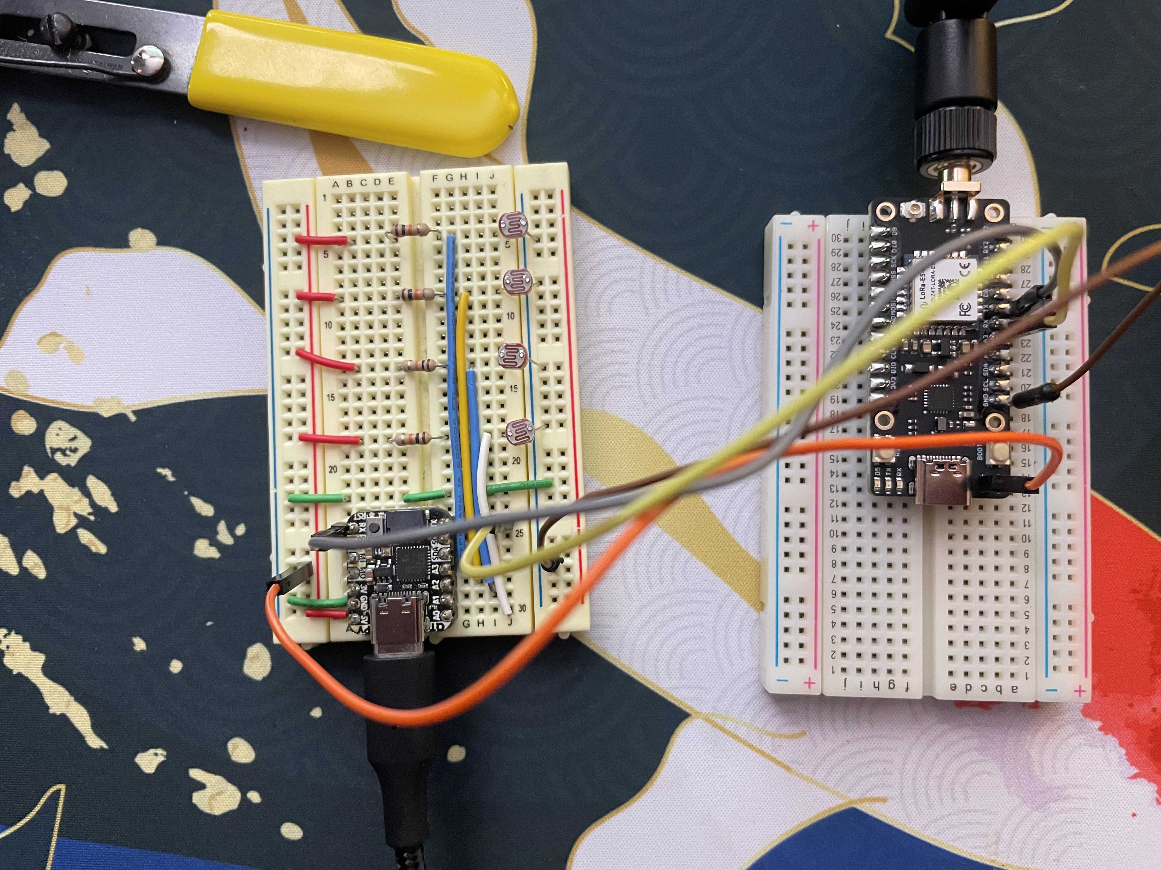
}After I got the communication working, I made a simple circuit on a breadboard and verified that I could read in all of the individual photoresistors.
The circuit was pretty straightforward, this configuration allows the analog inputs to read 1023 when they are completely blocked and a lower number as it gets brighter. These photoresistors go up to 20k Ohms so I selected a 10k Ohm resistor so that when the photoresistor is completely dark, we will read 2/3 of the voltage at the inputs. When it is completely lit and the photoresistor is close to 0 Ohms, we should read almost 0VDC.
Once I verified that all of the photoresistors read about the same, I hooked up the LoRa E5 Mini over serial and had it connect to the Things Network and start sending data.
RX on the QT Py goes to TX on the LoRa E5 Mini.
TX on the QT Py goes to RX on the LoRa E5 Mini.
5VDC on the QT Py goes to the + of the LoRa E5 Mini.
Ground on the QT Py goes to any ground on the LoRa E5 Mini.
Final ConstructionNow that all of the breadboard testing was done, I used a permaproto board to create a more robust and compact circuit.
I still had to solder on the + and - pins on the LoRa E5 Mini as well as the photoresistors.
Testing Protoboard VersionOnce all of the soldering was complete, I tested the system to make sure that the board was still functional.
As you can see, when I shine the light from my phone onto the board, I receive the readings on both the serial connection as well as on the Things Network.
This is my first attempt of creating an enclosure for this project:
I think the enclosure is much too small. I used https://www.festi.info/boxes.py/ABox?language=en to make the initial enclosure. If you have a CNC or a lasercutter, this website is a great help!
Future PlansConstruction of the enclosure to fit the board, photo resistors as well as an appropriately sized battery and then real world testing (it is currently very cold outside so I’m going to wait until the weather gets a little nicer).
Just an FYI, I received the LoRa-E5 mini board from Seeed Studio to try it out and make something cool. That being said:
To accelerate the development of IoT industry to the next level, Seeed is 100% sponsoring Wio-E5 projects with the Seeed Fusion PCB Assembly custom board for all hardware enthusiasts, designers, makers, and engineers around the world!Good ideas need to be discovered, and good projects deserve to be recognized, realized and widely disseminated! Each person is limited to two PCBA boards 100% completely FREE for one design, including PCB fabrication, the cost of parts, assembly and shipping. The design must include Wio-E5. To find out more about this events:https://www.seeedstudio.com/blog/2021/10/21/invigorate-your-inspiration-for-iot-with-lora-e5-and-free-seeed-fusion-pcba-prototypes/


_3u05Tpwasz.png?auto=compress%2Cformat&w=40&h=40&fit=fillmax&bg=fff&dpr=2)


Comments
Please log in or sign up to comment.