Soil Moisture Sensor is widely used sensors in the Smart Farming and by using a sensor like YL-69 or YL-38, you can transition into IoT in Agriculture. One of the great applications of Soil Moisture Sensors is to create an Automatic Irrigation System which can irrigate the farm based on the Soil Moisture.
In this Iot Project: Soil Moisture Sensor Arduino Tutorial, we will take up YL-69 Senor and Connect it to NodeMCU and transmit the data to https://thingsio.ai cloud and build a beautiful dashboard to monitor your Soil Moisture and extend it later to build an automatic irrigation system.
So, let’s get started.
Before getting started make sure you have
1. NodeMCU Board
2. YL-69 or YL-38 Sensor
3. basic free account on https://thingsio.ai
Step 1: Soil Moisture Sensor Description and ConnectionSoil Moisture sensing has two parts one is the actual sensor and second is the control board.
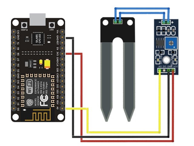
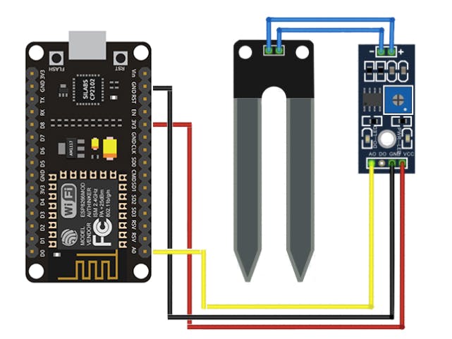
YL-39: Actual Soil Moisture Sensor, which is dipped int he the soil and which does the actual sensing, it is two wired out the sensor, you can say it is a differential sensor, this out is connected to the sensor control board.You need to connect the 2 header pins (+ and -) to the YL-38 soil moisture sensor control board as shown by the 2 blue wires above.
Soil Moisture Sensor Control Board:This board takes two-wire inputs from the YL-39 Soil Moisture Sensor and converts it into to digital and analog outputs. Totally it has four pins on the output side pins has 4 pins on the other side labelled VCC, GND, D0, A0.
VCC: Positive Voltage Power SupplyGND: GroundD0: Digital Out /////here we are not connecting this pin…A0: Analog Out, we only taking analog value from A0
Control Board to ESP8266 Development Board1. Connect VCC of the Control Board to 3V3 on the NodeMCU board ( Red wire )2. GND on the module to GND on the NodeMCU board ( Black wire )3. A0 from module to A0 on the Nodemcu (Yellow Wire)Now all the connections are done. Next step is to calibrate the sensor
Step 2: Calibrating the Soil Moisture SensorCalibrating the sensor has two parts, make sure you have a bowl of water with you handy as it involves dipping the sensor in the water and take the reading. the goal is to make sure sensor is functioning properly. make sure you are using tap water not Bisleri or distilled water as conductivity is distilled water is very low and sensor might not work properly.
Step 2.1: Running Sample NodeMCU code int he Arduino IDENow I’m going to connect my NodeMCU board to the laptop, I run windows 10 and fire up the Arduino IDE, compile the below code and run it.
////Create a new sketch in the Arduino IDE and paste the following code into the body: int sensor_pin = A0;int output_value ;void setup() {Serial.begin(115200);Serial.println("Reading From the Sensor ...");delay(2000); }void loop() {output_value= analogRead(sensor_pin);Serial.print("Moisture : ");Serial.print(output_value);Serial.print("\n");delay(1000); }
this will display sensor values in the serial monitor, take a note of the dry sensor reading.
Step 2.2: Calibrating the SensorNow that you have a functioning soil moisture sensor, how do you get some useful data out of it?
Take note of the number that flashes across the screen on your serial monitor inside of the Arduino IDE while your sensor is completely dry, it is usually 9XX if you have your soil moisture sensor plugged into 3V on your ESP8266 Development board. Next, completely submerge your soil moisture leads in a small cup of water. Be careful not to submerge the wires during this step as this could damage your electronic hardware.
As soon as you submerge your sensor in the water, keep an eye on the serial monitor. You will see the readings jump to a different value!!!!!
In mine (yours may be slightly different), a completely dry sensor gives a reading of about ~750, while a completely wet sensor reads consistently around ~180. Taking these numbers, we are going to add a few lines of code to our Arduino Sketch to map these values to a more familiar percentage (%).
First, we need to convert the values we are getting to a percentage, and we can do this using the map function.
output_value = map(output_value,750,180,0,100);
This simple function takes our 2 values and converts them from 0 – 100% based on their number between each other. The first number you put into the map function is the sensor value when it is completely dry, next comes the wet value. The following values are the map values, 0 being 0% and 100 being 100%.
Next, we can add a % symbol into the line being printed as shown.
Serial.print("%\n");
Your completely modified code should look like this before you push it to the development board:
int sensor_pin = A0;int output_value ;void setup() {Serial.begin(115200);Serial.println("Reading From the Sensor ...");delay(2000); }void loop() {output_value = analogRead(sensor_pin);output_value = map(output_value,750,180,0,100);Serial.print("Moisture : ");Serial.print(output_value);Serial.print("%\n");delay(1000); }
Now since the sensor is connected to nodemcu and calibrated we are ready to build the IoT Project and monitor the data on the IoT Platform.
I have made the entire IoT Tutorial below, please follow it end to end
NodeMCU Arduino code is hosted on the GitHub below is the link to the repositoryhttps://github.com/amruthp/esp32-arduino-code.git
Clone it and make the1. WiFi SSID & Password2. Device ID ( you will get it from your thingsio.ai account project page )3. Authorization token ( again this will be available from your thingsio.ai account )
ConclusionIf you followed the tutorial and made the correct changes, you should see the graph like below
Let me know how the tutorial went, please comment and like my tutorial and thanks for reading this.
Want to know what more you can do on https://thingsai.io read more on here
https://thingsai.io/blog/iot-tutorial-projects-esp8266-raspberry-pi-nodemcu-esp32


_3u05Tpwasz.png?auto=compress%2Cformat&w=40&h=40&fit=fillmax&bg=fff&dpr=2)
Comments
Please log in or sign up to comment.